Getting 12 volts from a 24-volt system with multiple batteries is possible through several methods. You can use simple approaches that involve tapping into just one battery in a series bank or using resistors to create a voltage divider. Still, these methods are inefficient and can reduce your battery life.
For clean, efficient voltage conversion from 24V down to 12V, a DC-DC converter circuit is the best approach.
This article will explore the pros and cons of these different methods for reducing 24 to 12 volts to power various devices and loads. We will also provide a tutorial for constructing a basic DC-DC converter using readily available components to provide stable, regulated 12V output from a higher 24V source.
Simple Methods
Some simple methods can obtain a lower voltage, like 12V, from a higher voltage dual battery 24V system. These simple approaches avoid the need for complex voltage conversion circuits. However, they also come with significant disadvantages that make them impractical for many applications.
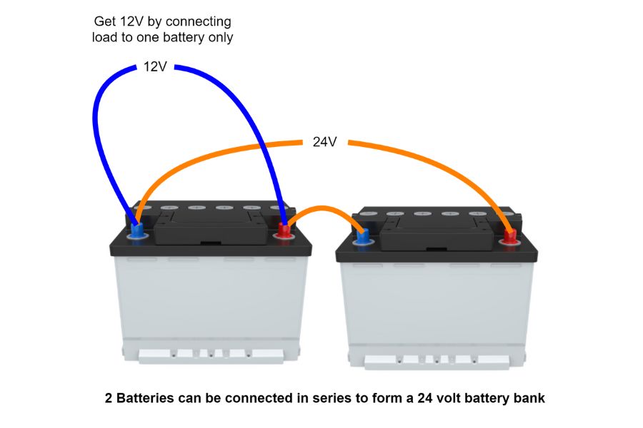
Connecting Load to One Battery in a 24V System
In a 24V system with two batteries wired in series, one simple method to obtain 12V is to connect the 12V load directly to just one of the two 12-volt batteries. This allows drawing power from a single 12V battery without any voltage conversion.
However, there are significant drawbacks to this approach that should be considered. Drawing current from only one battery in a series bank will cause the batteries to become unbalanced over time. The tapped battery will discharge faster while the other battery is left underutilized.
In addition, when charging the batteries, the untapped battery may end up overcharged as the charging system tries to fully charge the depleted tapped battery. This imbalance in charging and discharging is very detrimental to battery health and lifespan.
Steps to Connect to One Battery to Get 12 Vdc from a 24 Vdc System
Identify the 12V battery you want to tap for the 12V load
Connect the positive lead of the 12V load to the positive terminal of that battery
Connect the negative lead of the 12V load to the negative terminal of the same battery
Disadvantages of Using One Battery
Batteries wear unevenly – tapped battery wears out much faster
Imbalanced charging is required, reducing battery life
Total capacity is reduced by half since only one battery is used
Risk of excessive discharge currents on a single battery
The electrical system depends on both batteries operating evenly
Using Resistors to Reduce Voltage
Resistors can create a simple voltage divider circuit that reduces a higher voltage to a lower level. For example, resistors could be used to drop 24V down to 12V.
In a voltage divider, the input voltage is applied across a series of resistors. The voltage will be divided based on the ratio of the resistor values according to Ohm’s Law.
By selecting appropriate resistor values, any desired output voltage can be obtained. For a 24V to 12V drop, two equal-value resistors could be used.
While simple, using resistors to reduce voltage has significant disadvantages:
Very inefficient – wasting power as heat in the resistors
Not suitable for heavy equipment with a large current draw
Output voltage varies with load current due to voltage drop
Requires relatively large, high-wattage resistors
Resistors can overheat at higher load currents
Steps to Use Resistors to Drop Voltage
Determine the input voltage of your battery bank and the desired output voltage needed for the load. For example, dropping 24V to 12V.
Select resistor values to create the correct voltage divider ratio. For a 24V to 12V drop, choose two equal-value resistors.
On a breadboard or PCB, connect the two resistors in series across the positive and negative terminals of the battery bank.
Connect the load that needs the reduced voltage between the resistors. It will now receive the dropped voltage.
Calculate resistor power ratings to ensure they can handle the load current without overheating.
Consider adding a capacitor or other filtering to reduce the ripple on the output voltage.
DC-DC Converters
A DC-DC converter is an electronic circuit that converts a direct current (DC) source from one voltage level to another. It allows stable and efficient conversion of an input DC voltage to a different output DC voltage.
DC-DC converters temporarily store the input energy and then release it to the output at a different voltage. This is achieved using inductors and capacitors to store energy in magnetic and electric fields.
The most common types of DC-DC converter topologies are buck (step-down), boost (step-up), and buck-boost (step-up/down). A buck converter steps the voltage down, while a boost converter steps it up.
DC-DC converters have several advantages over simply connecting the load to one battery and resistive voltage dividers:
Much more efficient – wasting little energy as heat
Allows both stepping up and stepping down voltage
The output voltage remains constant under varying load
Available in compact IC package for simplicity
Wide input/output voltage range options
The high efficiency of DC-DC converters makes them well-suited for tasks like converting a 24V system down to 12V to power various devices and loads. Their flexibility and small size have led to widespread adoption in electronics.
Types of DC-DC Converters
Two main types of DC-DC converter topologies are linear regulators and switching regulators. Each has advantages and disadvantages for converting from one DC voltage to another.
Linear Regulator DC-DC Converters
A linear regulator uses a simple transistor circuit to drop excess voltage and regulate the output. It operates in the linear region of the transistor to maintain the desired output voltage.
Linear regulators have very simple circuit designs requiring few components beyond the regulating transistor. They also provide low-noise operation.
However, linear regulators are inefficient since power is wasted as heat dissipation across the transistor. They can only step down voltage, not step it up. The wasted power often requires large heat sinks at higher currents.
Pros
Linear regulators have a simple circuit design that is easy to construct and troubleshoot.
They provide clean, low-noise operation when converting voltage.
Cons
Linear regulators are very inefficient, with significant power wasted as heat.
They can only step down voltage, not increase it to a higher level.
Large heat sinks are often needed to handle heat at higher load currents.
Switching Regulator DC-DC Converters
A switching regulator converts power by temporarily storing input energy and then releasing it to the output at a different voltage. This is achieved using switches, inductors, and capacitors to store energy in magnetic and electric fields.
The high-frequency switching allows very efficient conversion, often 80-90%. Switching regulators can step-up or step-down voltage.
However, switching regulators are more complex designs and can produce higher noise due to the switching. There are many different switching topologies possible.
Pros
Switching regulators are very efficient, with up to 90% conversion efficiencies.
They can step up or step down the voltage as needed.
Cons
Switching regulator circuits are more complex than linear regulators.
They can generate more noise due to high-frequency switching.
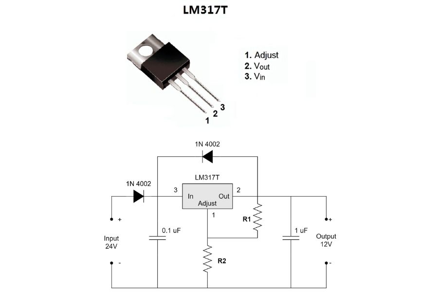
A Simple DIY DC-DC Converter Circuit to Get
A basic yet effective DC-DC converter can be built using an LM317T adjustable voltage regulator IC. The LM317T is designed to convert an input voltage between 3V to 40V down to a regulated output adjustable from 1.25V to 37V at up to 1.5A.
By selecting the appropriate resistors R1 and R2, the LM317T can be set to output any desired voltage within its range. For converting 24V down to 12V, resistor values would be chosen to divide the voltage in half. You can use an online calculator to find out the correct resistance values.
One possible combination is to set R1 = 240 ohm and R2=2000 ohm.
The circuit contains just a few main components – the LM317T regulator, input and output capacitors for filtering, and two resistors to set the output voltage. An optional heat sink can be added to allow higher power operation.
The capacitors help smooth out pulsations on the input supply and ripple on the output. The LM317T adjusts its internal resistance to maintain the programmed output voltage even with fluctuating load current.
Overall, this is a simple, low-component count DC-DC converter circuit that provides a regulated output voltage from a higher input voltage. Adjusting the output voltage as needed by swapping the resistor values is easy.
The main drawback is lower efficiency than a switching regulator design. However, an LM317T converter is a low-cost solution for low to moderate-power applications.
Steps to Build the DC-DC Converter
Select resistor values based on an LM317T resistor calculator to set the desired output voltage.
Assemble the circuit with input/output capacitors and LM317T placed on a heat sink.
Connect input voltage and measure output – adjust resistors if needed.
Add adequate heat sinking if operating at higher power.
Enclose in a proper enclosure for safety.
With just a few components, the LM317T adjustable regulator can create a functional DC-DC buck converter for stepping down 24V or other higher voltages to 12V or other desired lower voltages. The simple linear design provides easy adjustment and stable operation.
How useful was this post?
Click on a star to rate it!
Average rating 5 / 5. Vote count: 2
No votes so far! Be the first to rate this post.
We are sorry that this post was not useful for you!
Let us improve this post!
Tell us how we can improve this post?
charlesnoble
Here at Spheral Solar, I’m a hands-on solar power enthusiast, constantly exploring and experimenting with DIY solutions. I’m dedicated to sharing my discoveries, insights, and even the bumps I hit along the way, all in the pursuit of a more sustainable future.
Why Your 8 Volt Battery Won’t Charge (And How to Fix… by Charlesnoble February 25, 2026 Match your charger voltage to your battery’s 8-volt requirement, or risk permanent damage to your battery bank. Most standard chargers output 6V or 12V, making them incompatible with the less common 8V configuration found in certain golf carts, floor scrubbers, and older solar setups. Use a dedicated 8-volt charger with…
Why 6 Volt Batteries Might Be Your Solar System’s… by Charlesnoble February 20, 2026 Connect 6-volt batteries in series pairs to create 12-volt banks that deliver superior amp-hour capacity and longer lifespan than single 12-volt alternatives. This wiring configuration doubles your voltage while maintaining the individual battery capacity, giving you more usable power for off-grid applications. Most RV and camping solar setups benefit from…
Lifepo4 Voltage Chart: Understanding Battery… by Charlesnoble October 18, 2023 A LiFePO4 battery voltage chart displays how the voltage is related to the battery’s state of charge. These charts vary depending on the size of the battery—whether it’s 3.2V, 12V, 24V, or 48V. This article will dive deep into interpreting these charts and their practical implications. We’ll also cover the…
Your iPhone Doesn’t Need a Wall Outlet Anymore by Charlesnoble November 16, 2025 Charge your iPhone anywhere the sun shines by pairing a solar panel rated at minimum 10 watts with a portable battery bank that has USB output. I learned this the hard way during a week-long camping trip in Colorado when my flimsy 5-watt panel couldn’t keep up with my phone’s…
Why Your Solar Lights Keep Dying (and How 9V… by Charlesnoble January 25, 2026 Match your solar panel’s voltage output to your 9V battery’s charging requirements by selecting panels rated between 9-12 volts to prevent undercharging or damaging overcharge. Test your panel’s actual output with a multimeter in full sunlight before connecting any battery—you’ll often find advertised voltages don’t match real-world performance, especially on…
Why Your RV Solar System Isn’t Charging (And How to Fix It) by Charlesnoble May 6, 2026 Picture this: You’re parked at a stunning boondocking spot, miles from the nearest electrical hookup, and your RV batteries are draining fast. Your fridge starts warming, lights dim, and you’re left wondering if you’ll need to pack up and find a campground. I’ve been there, and it’s frustrating. RV solar…
Subscribe for handpicked DIY projects, exclusive tips, and giveaways.
A portable power station will typically run your camping devices for anywhere from a few hours to several days on a single charge, depending on what you’re powering and the station’s capacity. As for lifespan, most quality units last between 3 to 10 years before the battery degrades enough to need replacement. The distinction matters… Read more: Your Portable Power Station Won’t Last as Long as You Think (Here’s Why)
A J1772 solar charger combines a standard J1772 charging connector (the same Type 1 plug used by most North American EVs and electric bikes) with solar panels and battery components to create an off-grid or grid-supplemented charging system. You’ll need three core elements: solar panels (typically 400-800 watts for practical ebike charging), a battery storage… Read more: How to Choose a J1772 Solar Charger for Your Ebike: A Buying Guide
Installing a whole house ventilation system powered by solar takes about 6 to 8 hours for a moderately skilled DIYer and delivers continuous fresh air circulation without touching your electric bill. The core method involves mounting a solar panel on your roof to power an intake or exhaust fan, routing ductwork through your attic or… Read more: How to Install a Whole House Ventilation System Using Solar Power


")


")
")
")


")
")