Knowing how to wire an inverter to an RV breaker box allows for efficient electrical power utilization when camping or traveling in an RV.
Wiring a power inverter to your RV’s breaker box involves creating a connection between your battery bank, inverter, and RV’s breaker panel, often using changeover switches.
These switches enable seamless transition between shore, generator, and battery power, ensuring a consistent and safe electricity supply for mobile adventures.
In this article, we will simplify the process for you, explaining step-by-step how to install an inverter to your RV’s breaker system properly.
You will also need to gather the necessary tools – a multimeter, wire stripper, screwdriver, drill, and the appropriate wires and connectors for your specific inverter, battery bank, and breaker box.
Step 1: Setting Up the Inverter and Battery Bank
Select an optimal location for your battery bank and the RV inverter. To minimize voltage drops, keep them close together.
The chosen area should be free from moisture or excessive heat, well-ventilated, and easily accessible for maintenance or troubleshooting.
Secure the batteries and the inverter in place, typically by fastening them onto a suitable substrate like a wooden board or metal mounting bracket.
Step 2: Connecting the Inverter to the Battery Bank
Connect the batteries to the inverter using DC cables to create a DC power circuit.
First, use a multimeter to verify the polarity of the connections. The positive terminal on the battery should connect to the positive terminal on the inverter and vice versa.
Secure the connections and ensure the cables are safe from any potential damage.
If using multiple batteries, ensure they are arranged in the correct series-parallel configuration to provide the correct DC voltage.
Step 3: Connecting the Inverter to the RV Breaker Panel
Depending on the available electrical power supply options, several methods exist for connecting your battery inverter to the RV’s electrical system.
You can establish a direct connection or install a 2-way or a 3-way changeover switch.
The switch (a transfer switch) allows safe alternation between shore power and battery power, preventing back feed into the power grid – a potential hazard.
Installing the Inverter Directly
For a direct connection, strip a small insulation section from your wires.
Next, attach the positive (red) cable to the positive terminal of the main breaker on the RV breaker panel and the positive terminal of the inverter output. Don’t forget to install a fuse box on this positive wire.
Similarly, attach the negative (black) cable to the main breaker’s negative terminal and the inverter’s negative output terminal.
Installing a 2-Way Changeover Switch
To 2-way changeover switch can help you quickly switch between shore power and inverter. To install a 2-way changeover switch, do the following:
Start by connecting the live and neutral wires from the inverter output terminal to one of the input terminals on the switch.
Next, connect the AC power supply from the shore power source to the other input terminal. Use a circuit breaker box for safely connecting shore power to your electrical systems.
Wire the output terminals of the switch to the main breaker of your RV breaker box. Ensure that the output from the switch is connected to the input on the breaker box.
Finally, connect the ground wire to the ground terminal or the body of the changeover switch.
Installing a 3-Way Changeover Switch
If your RV has three potential power sources (AC shore power, an AC generator, and the inverter), you’ll need a 3-way changeover switch.
Begin by connecting the power from the AC shore power source to input 1 of the switch.
Connect the AC power from the generator to input 2.
Then, connect the AC power from the inverter to input 3.
Wire the AC output terminals of the switch to the main breaker of your RV breaker box.
Ensure the power from the AC shore power source and the AC generator is channeled through their respective circuit breakers.
The inverter wiring diagram is shown below:
Step 4: Setting Up the Battery Charging System
If your inverter includes a built-in charger, connect it to an external AC power source, such as a wall outlet. This arrangement allows the inverter to charge the batteries while connected to a shore power socket.
In cases where you have a separate battery charger and not an inverter/charger, you can still utilize an AC shoreline or an AC generator to charge your batteries. But you with need a converter for transforming AC power into DC power.
To easily switch between shore power and the generator, use a 2-way changeover switch.
You can also use solar panels to charge your batteries. In this case, you’ll need to connect the solar panels to a solar charge controller and then link the controller to the battery bank.
Ensure you install a fuse on the positive (red) wire for safety. Use this calculator to determine the right solar system size for your requirement.
The wiring diagram for a separate battery charging system is shown below:
Step 5: Powering On the Inverter and Testing Your Setup
After wiring the inverter to the breaker box and connecting the battery charger, it’s time to turn on the inverter. Ensure all connections are secure before doing so.
Switch the inverter on and ensure everything in your installation is functioning correctly.
Start by confirming whether the voltage on the DC system matches the inverter’s requirements. Next, switch on the breakers individually, checking each circuit’s functionality.
Finally, we want to test the system on AC load. Simply plug in your air conditioner or other AC appliances to test the system on the actual load.
Remember, this process can be complex, and the specifics can vary based on your particular RV, inverter, battery bank, and breaker box.
Always refer to the manufacturer’s instructions and consider consulting with a professional if needed.
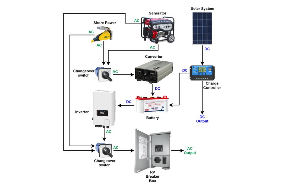
Understanding the Complete System
The RV electrical system operates through three primary sources: AC shore power, an AC generator, and a solar system.
The solar system generates DC power, which is managed and regulated by a solar charge controller before being used to charge the battery.
The AC shore power and AC generator also contribute to battery charging. However, since these sources produce AC electricity, a converter transforms AC into DC power, suitable for battery storage.
When the power from the battery is required, it must be converted back to AC before entering the RV breaker box. An inverter facilitates this conversion, changing DC power from the battery into usable AC power.
To effectively manage these power sources, a 3-way changeover switch is installed.
This switch allows seamless shifting between the AC shore power, the AC generator, and the inverter. This ensures efficient power management within your RV system.
Selecting the Right Wire Size for your Inverter
Choosing the correct wire size when wiring an inverter to your RV’s breaker box ensures safety, functionality, and efficiency.
The proper wire size will depend on several key factors, such as the output of the inverter, the distance from the inverter to the breaker box, and the amperage of the circuit. Follow the steps below to make the correct choice:
Determine the Current
Start by determining the current that the inverter will be producing. This information is usually stated in the product’s manual.
Alternatively, you can calculate it by dividing the inverter’s output power (in Watts) by the input voltage (in Volts). For example, if you have a 2000W inverter that supplies 230V, the current would be 8.7A.
Account for Power Factor and Efficiency
Next, consider the inverters’ efficiency and the AC circuit’s power factor.
Assuming a power factor of 0.8 and an inverter efficiency of 90%, the current flowing through the wire would increase to 12.1A.
Add Safety Margin
Next, add a safety factor to your calculations. This will cater to unexpected overloads, inefficiencies, or potential expansions in the future.
A margin of 25% is a good starting point. With this safety factor, the current for the example above will increase to 15.1A.
Select the Correct Wire Size
After finding the maximum current that will pass through the wires, refer to a relevant wire sizing chart to determine the required wire size.
These charts list the safe carrying capacity (in Amps) of different wire gauges under various conditions.
Always choose a wire size that can safely carry the maximum current that your inverter will produce. The American Wire Gauge (AWG) wire selection chart is given below:
The chart lists two types of wiring configurations: chassis wiring and power transfer.
The chassis wiring arrangement typically involves individual routing of each wire. This differs from power transfer wiring, in which wires are laid out in bundles.
Therefore, chassis wiring allows for superior cooling, resulting in the wires carrying more current.
For the above example, the minimum AWG gauge needed is #18 for chassis wiring and #9 for power transfer.
Verify the Voltage Drop
If the distance between your inverter and breaker box is long, you may need to choose a larger wire size to compensate for the voltage drop. As a rule of thumb, aim for a voltage drop of less than 3% for the AC side wiring.
To calculate the voltage drop in wiring, read the resistance (Ω / km or Ω / kft) from the table above. The voltage drop is then calculated as follows:
For our example, the resistance of the selected AWG#9 wire is R = 20.948 Ω / km.
Assuming a wire length of L = 2 m, the voltage drop can be calculated for current I = 15.1 A is V = 0.63 V, which is just 0.28% of 230 V.
How useful was this post?
Click on a star to rate it!
Average rating 5 / 5. Vote count: 2
No votes so far! Be the first to rate this post.
We are sorry that this post was not useful for you!
Let us improve this post!
Tell us how we can improve this post?
charlesnoble
Here at Spheral Solar, I’m a hands-on solar power enthusiast, constantly exploring and experimenting with DIY solutions. I’m dedicated to sharing my discoveries, insights, and even the bumps I hit along the way, all in the pursuit of a more sustainable future.
Why Your Motorhome Electrical System Keeps Failing… by Charlesnoble November 18, 2025 Picture this: You’re three days into a dream cross-country trip when your lights flicker, the refrigerator stops cooling, and you’re left wondering whether to call for expensive roadside assistance or figure it out yourself. I’ve been there, and here’s what I wish someone had told me before my first electrical…
Why Your RV Appliances Keep Tripping the Breaker… by Charlesnoble November 17, 2025 Turn off shore power and disconnect your battery bank before touching any wire in your RV—this single step prevents the most common DIY electrical accidents. Check your circuit breaker panel ratings against your actual appliance loads, because that microwave drawing 1500 watts on a 15-amp circuit is exactly why you’re…
Should an RV Inverter Be Left on When Plugged In? by Charlesnoble October 31, 2023 Generally, RV inverters should be turned off when not in use to avoid unnecessary battery drain. However, whether an RV inverter should be left on or off when plugged in depends on several factors, primarily the type of inverter and the manufacturer’s recommendations. In this comprehensive guide, we’ll look in-depth…
Wire Your RV Tow Vehicle the Right Way (7-Pin… by Charlesnoble May 14, 2026 Identify the seven wires in your RV connector by their standard color codes: brown carries running lights, yellow handles left turn signal and brake, green manages right turn signal and brake, white serves as ground, blue powers electric brakes, black provides 12V battery charge, and red or purple connects auxiliary…
Why Your RV Battery Dies Overnight (And How a 55 Amp… by Charlesnoble December 5, 2025 Your RV’s lights are flickering, the refrigerator isn’t keeping food cold, and your phone charger barely works. Sound familiar? That frustrating power struggle often points to an undersized or failing power converter, and upgrading to a 55 amp RV power converter might be exactly what you need. Here’s what’s happening:…
Why Quiet Camping Generators Beat Solar (And When… by Charlesnoble November 27, 2025 Choose a generator rated at 50-55 decibels or lower to ensure peaceful camping without disturbing wildlife or neighboring campers—models with inverter technology automatically adjust engine speed based on power demand, reducing noise significantly compared to conventional generators. Look for four-stroke engines with enclosed designs and rubber mounting feet that absorb…
Subscribe for handpicked DIY projects, exclusive tips, and giveaways.
Installing a whole house ventilation system powered by solar takes about 6 to 8 hours for a moderately skilled DIYer and delivers continuous fresh air circulation without touching your electric bill. The core method involves mounting a solar panel on your roof to power an intake or exhaust fan, routing ductwork through your attic or… Read more: How to Install a Whole House Ventilation System Using Solar Power
Connecting your SolarEdge inverter to your home network via Ethernet cable takes about 15 minutes and gives you real-time access to your system’s performance data from any device with internet access. You’ll plug a standard Ethernet cable into the RJ45 port on your inverter (usually labeled “LAN” or “Ethernet”), run it to your router, and… Read more: How to Connect SolarEdge to Ethernet for Seamless System Monitoring
You can build a DIY solar tube for $50 to $150 and start harvesting natural daylight in a weekend. This simple project combines a reflective tube, clear dome, and diffuser to channel sunlight from your roof into dark interior spaces, delivering illumination equivalent to multiple bulbs without electrical costs or ongoing energy consumption. I remember… Read more: How to Make DIY Solar Tubes for Free Natural Lighting in Your Home


")
")

")
")
")
")
")

")
")
")


