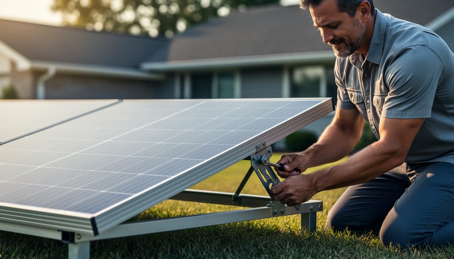
Why Your DIY Solar System Needs Proper Grounding (Before Something Goes Wrong)
Updated:
Ground your solar system before you connect a single wire—improper grounding has destroyed thousands of dollars in equipment and created deadly shock hazards in homes just like yours. I learned this the hard way when a lightning strike fried my neighbor’s ungrounded inverter, teaching me that grounding isn’t optional paperwork but the invisible safety net protecting your family and investment.
Think of grounding and bonding as your electrical system’s emergency exit. Grounding provides a direct path for fault currents to reach the earth, tripping breakers before wires overheat or equipment explodes. Bonding connects all metal components together so they share the same electrical potential, preventing voltage differences that could shock you when touching two metal surfaces simultaneously. Most DIYers confuse these terms, but understanding both is essential before installing panels, inverters, or battery systems.
The confusion stems from conflicting information—your inverter manual shows one diagram, local codes require something different, and online forums offer twenty contradictory opinions. This creates dangerous knowledge gaps where installers either skip grounding entirely or create elaborate systems that violate code without realizing it.
This guide cuts through the confusion with component-specific instructions, real-world examples, and verification methods you can perform yourself. You’ll learn exactly which wires go where, what the inspector checks, and when to call a licensed electrician—because proper grounding means the difference between a system that protects your home and one that becomes its biggest hazard.
What Grounding and Bonding Actually Mean (In Plain English)
Proper bonding connections between solar panel frames ensure electrical safety by maintaining the same potential across all components.
Grounding: Your System’s Safety Valve
Think of grounding as your electrical system’s emergency escape route. When something goes wrong—maybe a wire comes loose inside your solar inverter or lightning strikes nearby—electricity needs somewhere safe to go. Without proper grounding, that somewhere could be you.
Here’s how it works: grounding creates a low-resistance pathway that directs fault currents straight into the earth. When an electrical component malfunctions and sends current where it shouldn’t go, the grounding system gives that energy a direct route to ground. This rapid flow of current trips your circuit breaker almost instantly, cutting power before anyone gets hurt.
I learned this lesson early in my solar journey when a friend’s poorly grounded system gave him a nasty shock while cleaning his panels. The equipment ground wire had corroded at the connection point, leaving no safe path for a fault. After that incident, he called an electrician—and I became obsessive about checking my own grounding connections.
In a solar setup, grounding protects both people and expensive equipment. It prevents dangerous voltage buildup on metal frames and enclosures, reduces fire risk from electrical arcing, and helps your system handle voltage surges from storms or grid fluctuations. Think of it as insurance that pays out instantly when disaster strikes.
Bonding: Keeping Everything at the Same Electrical Potential
While grounding provides a safety path to the earth, bonding ensures all the metal parts in your solar system are connected together at the same electrical potential. Think of it like a team holding hands—everyone stays together, so dangerous voltage differences can’t develop between components you might touch.
Here’s why this matters: Imagine your solar panel frames are at one voltage and your inverter case is at another. If you touch both simultaneously, you become the path for that voltage difference to equalize—not a pleasant experience. Bonding prevents this by connecting all metal surfaces together with conductors, typically copper wire or specialized bonding straps.
In your solar installation, you’ll bond equipment frames, panel mounting rails, inverter enclosures, battery racks, and even metal conduit. These bonding connections create what electricians call an “equipotential plane”—a fancy term meaning everything metal is at the same electrical level.
I learned this lesson early in my DIY journey when I felt a tingle touching my inverter and panel frame simultaneously. Turned out my bonding connections had loosened. After properly reconnecting everything, that uncomfortable sensation disappeared. This taught me that bonding isn’t just code compliance—it’s about making your system genuinely safe to work around and maintain for years to come.
Why Your Solar Setup Is Different from House Wiring
The DC vs. AC Grounding Challenge
When I first added solar panels to my home, I assumed grounding was grounding—just connect everything to earth and call it done, right? Not quite. I quickly learned that DC systems operate fundamentally differently than the AC circuits powering your home, and those differences matter significantly for safety.
Here’s the core issue: DC electricity doesn’t alternate direction like AC power. It flows continuously in one direction, which means any grounding faults behave differently. In AC systems, the alternating current helps certain protective devices like circuit breakers detect problems quickly. With DC, especially at the higher voltages from solar panel strings (often 300-600 volts), faults can be harder to detect and more dangerous if not properly addressed.
Solar panels and battery systems also introduce new concerns. Panels are exposed to weather and can develop leakage currents over time. Batteries store massive amounts of energy that could discharge catastrophically through improper ground paths. Additionally, many modern inverters use transformerless designs that require specific grounding configurations to function safely.
Your DC grounding strategy needs to account for equipment grounding (protecting you from shocks), system grounding (establishing a reference point), and ground fault protection devices specifically designed for DC circuits. These aren’t optional extras—they’re essential safety layers that work together differently than your home’s traditional AC system.
When Two Grounding Systems Meet
Here’s something I learned the hard way during my first solar installation: your home already has a grounding system, and your solar setup needs to play nicely with it, not fight against it. Think of it like introducing two dogs who need to become friends rather than creating territorial disputes.
Your existing home grounding system typically includes a ground rod (or multiple rods) driven into the earth near your main electrical panel, connected through your grounding electrode conductor. When you add solar panels, inverters, and batteries, they need to tie into this same system at a single point, usually your main service panel. This is called a “common grounding point,” and it’s crucial for safety.
The biggest mistake I see fellow DIYers make is creating multiple, separate grounding paths. Maybe they drive a new ground rod just for the solar array because it seems convenient, or they connect the inverter ground to a different location than the main panel. This creates what electricians call “ground loops,” which can cause equipment damage, interference, or worse, safety hazards during lightning strikes or electrical faults.
The golden rule: everything grounds back to your home’s main grounding electrode system. Your solar components should bond together and then connect to that existing infrastructure, creating one unified protective network.
The Essential Components of PV/ESS Grounding
Equipment Grounding Conductors (EGC)
Equipment Grounding Conductors are the safety heroes of your electrical system—those green or bare copper wires you see running throughout your installation. Think of them as emergency escape routes for stray electrical current. When I first installed my solar system, I’ll admit I was tempted to skimp on these wires since they don’t carry power under normal conditions. But here’s the thing: they’re literally life-savers when something goes wrong.
These conductors connect metal equipment frames, junction boxes, inverter enclosures, and racking systems back to your main grounding system. If a hot wire ever touches a metal surface, the EGC provides a low-resistance path that trips your breaker immediately, protecting you from shock.
Sizing matters here. For most residential solar circuits with 20-amp breakers, you’ll need 12-gauge copper EGC. Larger circuits require proportionally larger conductors—consult NEC Table 250.122 for specifics. Never downsize these wires to save money. I use our wire sizing calculator to double-check my work every time.
Remember, every piece of metal equipment needs its own connection. No daisy-chaining or relying on mounting bolts alone. Use proper grounding lugs, keep connections tight, and verify continuity with a simple multimeter test.
Grounding Electrode System
Your grounding electrode system is what physically connects your electrical setup to the earth itself. Think of it as the anchor that safely dissipates fault currents and lightning strikes into the ground.
The most common electrode is the ground rod, typically an 8-foot copper-clad steel rod driven vertically into the soil. If your home already has a ground rod from your main electrical panel, you can often use that existing electrode for your solar system too, as long as it meets current code requirements. However, many DIYers discover their existing rod doesn’t meet today’s standards or that their solar installation is far enough away to require its own electrode.
Ground plates offer an alternative in rocky soil where driving rods becomes impractical. These copper or galvanized plates bury horizontally at least 30 inches deep with minimum surface area requirements.
Charles here: I learned the hard way that soil conductivity matters tremendously. Sandy, dry soil often requires two ground rods spaced at least 6 feet apart to achieve proper resistance, while moist clay might work with just one.
Whatever electrode you use, proper ground rod installation requires secure connections using listed clamps and appropriate wire sizing, typically 6 AWG copper minimum for most residential solar systems.
Ground rods provide the essential connection between your electrical system and the earth, dissipating fault currents safely.
Bonding Jumpers and Lugs
When I first started bonding my solar components together, I felt like I was assembling a high-stakes electrical puzzle. The good news? Once you understand the right hardware, it’s actually straightforward.
Bonding jumpers are flexible copper wires or braided straps that connect your equipment to create a continuous electrical path. For most residential solar setups, you’ll need 6 AWG or larger bare copper wire for these jumpers. Think of them as the bridges that tie everything together into one safe, grounded system.
Bonding lugs are the connectors that attach these jumpers to your equipment. Most solar panels come with pre-drilled bonding holes, and you’ll use ring terminal lugs secured with stainless steel bolts. Here’s a tip from my own installation: don’t skimp on quality here. Cheap lugs corrode quickly, especially outdoors.
For inverters and charge controllers, check your manufacturer’s instructions for designated bonding points. Battery enclosures typically have dedicated grounding studs where you’ll attach lugs directly to the metal frame.
One mistake I made early on was mixing metals, which can cause corrosion. Stick with copper lugs on copper wire, and use anti-oxidant paste on all connections. This simple step prevents future headaches and ensures your system stays safely bonded for decades.
Step-by-Step: Grounding Your Solar Panel Array
Bonding Your Panel Frames Together
Once your panel frames are securely mounted, you’ll need to electrically connect them all together—this is bonding. Think of it like creating one continuous electrical pathway through your entire solar array.
Most installers use specialized bonding hardware for this job. Bonding clips are popular because they’re designed to bite through anodized coatings on aluminum frames, creating that crucial metal-to-metal contact. These spring-loaded clips typically attach between adjacent panel frames and require no drilling.
If your panels have pre-drilled bonding holes, you can use bonding lugs with stainless steel star washers. Those star washers are important—their sharp teeth pierce through any oxidation or coating to reach bare metal underneath. I learned this the hard way years back when Charles mentioned checking continuity on a friend’s system; we discovered several panels weren’t actually bonded because smooth washers were used instead of star washers.
When installing bonding hardware, make sure contact surfaces are clean and free of paint, excessive oxidation, or debris. A light scuff with a wire brush helps if frames look heavily oxidized. After connecting each panel, use a multimeter set to continuity or low resistance mode to verify the bond—you should see near-zero resistance between any two frames in the array.
Finally, run a bonding conductor from this interconnected frame network back to your grounding electrode system, completing the protective pathway.
Running the Grounding Conductor to Your System
Once your grounding electrode system is in place, you need to connect it to your solar array and electrical panel. Think of this conductor as the critical highway that carries fault currents safely to the earth.
For most residential solar systems, you’ll use a copper conductor sized according to NEC Table 250.66. Here’s the practical breakdown: if your largest service conductor is 2 AWG or smaller, your grounding electrode conductor needs to be at least 8 AWG copper. Larger systems may require 6 AWG or even 4 AWG. When in doubt, go bigger—it’s cheap insurance.
The routing matters as much as the sizing. Run your grounding conductor in as straight a line as possible from your array to the grounding electrode. Avoid sharp bends that could create high-impedance paths during a fault. I learned this the hard way when my first installation failed inspection because I’d snaked the conductor unnecessarily around a corner.
Secure the conductor every 4-6 feet using appropriate staples or clips, especially if running along a wall or through conduit. At connection points, use listed grounding lugs or clamps—never twist wires together or use hardware store clamps not rated for electrical grounding.
Grounding Your Inverter and Charge Controller Correctly
Understanding Equipment Grounding Terminals
Every inverter and charge controller has a grounding terminal, typically marked with a ground symbol or “GND” label. These terminals aren’t optional connections you can ignore because they seemed confusing in the manual. They’re your primary safety mechanism that creates a path for fault currents to safely reach earth.
When I installed my first charge controller years ago, I’ll admit I almost skipped the grounding terminal because everything seemed to work fine without it. That was dangerously wrong thinking. Without proper grounding, a single insulation failure could energize your entire system’s metal components, creating a serious shock hazard.
To identify the grounding terminal, look for a green screw terminal or lug point, often located on the chassis or a designated grounding bar. It’s usually separate from your positive and negative DC connections. Some equipment has internal grounding through mounting screws, but always verify this in your specific model’s documentation rather than assuming.
The connection itself is straightforward: use properly sized bare copper wire, attach a ring terminal, and secure it firmly to the grounding terminal. This wire then connects to your system’s grounding electrode through your main grounding bus bar. Think of it as creating an intentional “escape route” for electrical problems, directing dangerous currents away from people and into the earth where they belong.
When and How to Bond Neutral (If Required)
Here’s the tricky part that trips up a lot of DIYers: deciding whether your inverter needs a neutral-ground bond. Think of this bond as the single point where your system’s neutral wire connects to ground, establishing a reference point for the entire electrical system.
The golden rule is simple: you need exactly one bond in your system, no more, no less. In a typical grid-tied home, this bond already exists at your main service panel. Adding another bond at your inverter creates what electricians call a “double bond” or “multiple ground fault path,” which can cause nuisance tripping, equipment damage, and dangerous ground loop currents.
Here’s when you would bond at the inverter: if you’re running a true off-grid system with no utility connection, your inverter becomes the first point of disconnect, so it needs the bond. Some inverters have a removable bonding jumper or switch specifically for this purpose.
I learned this lesson the hard way years ago when I couldn’t figure out why my backup system kept tripping. Turns out I had created a double bond without realizing it. Once I removed the bond at the inverter, everything worked perfectly.
If you’re unsure, consult your inverter’s manual and consider hiring an electrician to verify your configuration. Getting this wrong creates real safety hazards.
Battery Storage Grounding: Special Considerations
Grounding Battery Enclosures and Racks
When I first installed my battery bank, I nearly overlooked grounding the metal enclosure itself—a mistake that could’ve been dangerous. Just like any metal component in your system, battery enclosures and racks must be properly bonded to prevent them from becoming energized during a fault.
Start by identifying a solid grounding point on your metal enclosure, typically a pre-drilled hole with a grounding lug symbol. Use a bonding jumper wire (typically 6 AWG copper minimum) to connect this point directly to your system’s grounding bus bar. If your batteries sit on a metal rack, bond each rack section together using bonding jumpers between the metal frames, then connect one point of the rack to your grounding system.
This step is particularly crucial for battery storage safety in off-grid setups where batteries store significant energy. The enclosure bonding creates a low-resistance path that directs fault currents safely to ground, preventing shock hazards if internal components malfunction.
Remove any paint or coating at connection points to ensure metal-to-metal contact, and use star washers to maintain tight connections that resist loosening over time. Double-check all connections are secure—a loose bond is almost as dangerous as no bond at all.
DC System Grounding Options
When setting up a solar system, you’ll encounter two main DC grounding approaches: grounded systems (where one conductor connects to ground) and ungrounded systems (which rely on isolation monitoring). Here’s my straight talk after years of tinkering: unless you’re an experienced electrician, stick with your manufacturer’s specifications.
Modern inverters and charge controllers are engineered for specific grounding configurations. Many grid-tie inverters require ungrounded DC input because they perform their own ground-fault detection. Off-grid systems often use grounded negative conductors. Mixing approaches or improvising can create dangerous ground loops, nuisance faults, or even void your warranty.
I learned this the hard way when I “improved” a friend’s system by adding an extra ground point. Result? Constant error codes and a frustrated manufacturer tech explaining why my creativity actually compromised safety monitoring.
Check your equipment manuals first. They’ll specify whether to ground the positive, negative, or neither DC conductor. When in doubt, consult the manufacturer’s technical support before modifying anything. Your safety and system reliability depend on following their tested designs.
Common Grounding Mistakes That DIYers Make (And How to Avoid Them)
Using the Wrong Wire Size or Type
I learned this lesson the hard way during my first solar installation when I used what looked like perfectly good wire—only to discover later it was undersized for my system’s grounding needs. Here’s the thing: your grounding conductor isn’t just any wire. It needs to handle fault currents safely without overheating or failing.
Aluminum wire can be tempting because it’s cheaper, but it oxidizes over time, creating resistance that compromises your ground connection. For residential solar systems, stick with copper grounding conductors—they’re more reliable and code-compliant in most situations.
Size matters significantly here. An undersized grounding wire acts like a bottleneck during a fault, potentially melting or sparking instead of safely directing current to earth. The National Electrical Code provides sizing tables based on your largest circuit breaker or fuse. For most home solar systems with 200-amp service, you’ll typically need at least 6 AWG copper wire for your grounding electrode conductor, though larger systems may require 4 AWG or bigger.
My recommendation? Always round up when in doubt. That extra copper provides peace of mind and ensures your system stays protected as electrical codes evolve.
Poor Connections and Corroded Terminals
I learned this lesson the hard way during my first solar installation—six months after everything was running beautifully, I noticed intermittent system shutdowns. The culprit? A grounding connection that had developed a thin layer of corrosion, creating resistance where there should have been a solid electrical path. Even the best grounding system fails if connections aren’t maintained properly.
Grounding connections must be tight and clean to work effectively. When copper meets moisture and air, corrosion forms naturally, acting like an insulator between surfaces. This is one of those critical system mistakes that builds slowly over time.
Prevent this by using stainless steel hardware or corrosion-resistant connectors specifically rated for outdoor electrical use. Apply an anti-oxidant compound (available at any electrical supply store) to bare copper connections before tightening. When installing, ensure each connection is torqued according to manufacturer specifications—finger-tight isn’t enough.
Schedule annual inspections of all accessible grounding connections. Look for green or white powdery residue indicating corrosion. If you spot any, disconnect power, clean the surfaces with a wire brush, reapply anti-oxidant compound, and reconnect firmly. Your grounding system is your safety net—keep it in pristine condition.
Corroded grounding connections compromise safety and require immediate attention to maintain proper electrical protection.
Skipping Bonding Between Components
I learned this lesson the hard way during my first solar installation. I mounted my inverter to a metal sub-panel using stainless steel bolts and assumed the connection was solid. Everything looked great until my inspector explained that mounting hardware doesn’t guarantee electrical continuity.
Here’s the reality: paint, rust, thermal expansion, and vibration all create resistance between metal surfaces. Those bolts holding your equipment? They’re designed for mechanical strength, not electrical bonding. Over time, even slight oxidation can turn what looks like a solid connection into an electrical insulator when you need that fault current path most.
The solution is straightforward: use dedicated bonding conductors with proper lugs or connectors that penetrate any coatings and create metal-to-metal contact. Every metal component in your system, from junction boxes to equipment frames to conduit, needs its own intentional bonding connection. Think of it as insurance. Those extra few minutes installing proper bonding wires could prevent equipment damage or worse during a fault condition. Don’t trust appearances or assume mechanical connections equal electrical continuity.
Testing Your Grounding System: Simple Checks You Can Do
Visual Inspection Checklist
Regular visual checks of your grounding system can catch problems before they become safety hazards. Start by examining all connections—they should be tight and snug with no wiggle room. I learned this the hard way when a slightly loose ground rod clamp caused intermittent voltage issues in my own system.
Look for proper wire routing next. Ground wires should follow direct paths without sharp bends that could stress the copper. Check for corrosion, especially on exposed copper connections—that greenish buildup isn’t just ugly, it creates resistance that degrades your protection. White or crusty deposits around clamps also signal trouble.
Inspect wire insulation for cracks, nicks, or sun damage. Green or bare copper ground wires should be properly sized and not frayed. At your main service panel, verify the ground and neutral buses are properly bonded (or separated, depending on whether it’s your main or a subpanel).
Check ground rod clamps haven’t worked loose from soil settling, and look for any disconnected jumper wires between metal components. Document what you find with photos for future reference.
Regular testing with a multimeter verifies that all grounding connections maintain proper electrical continuity throughout your system.
Using a Multimeter to Verify Continuity
A multimeter is your best friend when verifying that everything’s properly bonded. Set your multimeter to the continuity setting, which usually looks like a sound wave symbol. When I first tested my solar array, I was amazed how this simple $20 tool gave me such confidence in my work.
Start by touching one probe to your main grounding electrode (the ground rod) and the other to each piece of equipment’s grounding point. You should hear a beep indicating continuity. No beep? That’s a red flag requiring immediate attention. Next, check resistance between bonded components. You’re looking for readings under 0.5 ohms between any two bonded metal parts.
Test from your inverter chassis to the equipment grounding conductor, then to nearby metal components like racking and junction boxes. Everything should show continuity. This verification step catches loose connections or corroded bonds before they become safety hazards. Remember, proper bonding means electricity always has a safe path home during faults, protecting both you and your equipment.
When to Call a Professional (And What Inspectors Look For)
Let me share something I learned the hard way: there’s a significant difference between understanding grounding concepts and actually implementing them safely. I once felt confident enough to handle my system’s grounding upgrades, but a friendly inspector pointed out three issues I’d completely missed—issues that could have caused real problems down the line.
Here’s the honest truth about DIY limits: you can absolutely learn grounding theory, identify components, and even plan your system layout. However, any work that involves your main electrical panel, service entrance conductors, or modifications to your existing home grounding system requires a licensed electrician. Period. Most jurisdictions also require professional installation and inspection for grid-tied solar systems, regardless of your skill level.
When electrical inspectors visit your site, they’re checking specific grounding elements with practiced eyes. They’ll verify that your ground rod depth meets code (typically 8 feet), confirm proper bonding between all metal components, check conductor sizing against charts, and ensure your grounding electrode system connects correctly to your main panel. They’ll also look for proper torque on connections, appropriate wire routing, and correct labeling—details that seem minor but matter enormously for safety and code compliance.
You should definitely call a professional before doing any work if you’re uncomfortable with electrical systems, if your project involves the main panel, or if local codes require it. Also reach out if you’re unsure about proper conductor sizing, need guidance interpreting NEC requirements for your specific setup, or simply want peace of mind. Professional electricians can often complete in hours what might take you days of research and troubleshooting—and they carry insurance for those just-in-case moments.
Getting your grounding and bonding right isn’t just about checking boxes on an inspection list. It’s about creating a system that protects your family, your home, and your investment in solar energy for years to come. I know it can feel overwhelming when you’re staring at NEC code books and trying to figure out wire gauges, but here’s the truth: every professional electrician started exactly where you are now, learning these principles one connection at a time.
The beauty of taking your time with grounding is that it’s one of those foundational elements you can genuinely feel good about. When you torque down that last grounding lug properly or verify continuity with your multimeter, you’re building something that matters. You’re not cutting corners, and that makes all the difference.
I’ve been working with solar installations for years, and I still double-check my grounding connections. There’s no shame in taking it slow, consulting with a licensed electrician when you’re uncertain, or even having someone inspect your work before energizing the system. The best DIYers I know are the ones who recognize when to ask for help.
I’d love to hear about your grounding experiences in the comments below. What challenges did you face? What resources helped you most? Your story might be exactly what someone else needs to hear to tackle their own installation confidently. Remember, we’re all learning together, and every safe installation makes our solar community stronger.
How useful was this post?
Click on a star to rate it!
Average rating 0 / 5. Vote count: 0
No votes so far! Be the first to rate this post.
We are sorry that this post was not useful for you!
Let us improve this post!
Tell us how we can improve this post?
charlesnoble
Here at Spheral Solar, I’m a hands-on solar power enthusiast, constantly exploring and experimenting with DIY solutions. I’m dedicated to sharing my discoveries, insights, and even the bumps I hit along the way, all in the pursuit of a more sustainable future.
This Single Mistake Could Destroy Your Entire Solar… by Charlesnoble January 4, 2026 Ground your lightning protection system with at least two 8-foot copper-clad ground rods driven into moist soil and spaced 16 feet apart, then bond them together with 6 AWG bare copper wire. This creates the essential foundation that channels lightning strikes safely into the earth, protecting your solar panels, inverter,…
Why Your Solar Ground Rod Might Be Too Short (And… by Charlesnoble January 15, 2026 Drive your 8-foot copper-clad steel grounding rod at least eight feet into the earth, or to the depth where you meet solid bedrock. This isn’t arbitrary—the National Electrical Code requires this specific length because it ensures your solar panels and battery storage system have a reliable path to dissipate dangerous…
Why Your PV Wire Management Could Fail Inspection… by Charlesnoble April 9, 2026 Route your PV wires through UV-resistant conduit within 18 inches of leaving the solar array, securing it every 3 feet with proper clamps to prevent wind damage and code violations. This single step prevents 80% of the wire degradation issues I’ve seen in DIY solar installations over the past decade.…
Why Your Solar Conduit Installation Could Start a… by Charlesnoble March 27, 2026 Measure your conduit run before purchasing materials by mapping the exact path from your solar array to the inverter and battery location, accounting for a 10% waste factor and additional length for bends. PVC electrical conduit remains the most cost-effective protective solution for DIY solar installations, but improper installation creates…
Why Your 6-Wire Solar Setup Needs the Right Conduit… by Charlesnoble March 6, 2026 Measure your wire gauge and count of six conductors before selecting conduit—most residential solar installations running six AWG 10 wires require 1-inch conduit, while six AWG 6 wires need 1.5-inch conduit, and six AWG 2/0 wires demand 2.5-inch conduit minimum. Calculate fill capacity using the 40% rule for three or…
Don’t Risk Your Life Installing Solar Panels: Fall… by Charlesnoble December 26, 2025 Secure yourself with a personal fall arrest system before stepping onto any roof pitch over 4:12—that’s a harness, lanyard, and proper anchor point rated for 5,000 pounds per worker. Install temporary roof anchors at the ridge line or use permanent mount anchors if you’re planning multiple trips up for maintenance,…
Subscribe for handpicked DIY projects, exclusive tips, and giveaways.
Position your solar panels at an angle equal to your latitude for year-round performance, or adjust seasonally by adding 15 degrees in winter and subtracting 15 degrees in summer to capture maximum sunlight during each season’s sun path. Use a simple angle finder app on your smartphone against the back of your panel to verify… Read more: The Right Tilt Angle Can Boost Your Solar Panel Output by 30% (Here’s How to Find It)
Route your PV wires through UV-resistant conduit within 18 inches of leaving the solar array, securing it every 3 feet with proper clamps to prevent wind damage and code violations. This single step prevents 80% of the wire degradation issues I’ve seen in DIY solar installations over the past decade. Group your positive and negative… Read more: Why Your PV Wire Management Could Fail Inspection (And How to Fix It)
Understand that 6000 volts sounds terrifying but delivers surprisingly low amperage—typically around 120 milliamps for just 3/10,000th of a second per pulse. This combination creates an unforgettable shock that trains animals to avoid the fence without causing lasting harm. The voltage pushes current through thick fur and hide, while the minimal amperage and microsecond duration… Read more: Why 6000 Volts Won’t Kill Your Livestock (But Will Stop Predators Cold)


")
")
")
")
")

")
")
")
")
")