Why Your Solar Panels Need Proper Grounding (And How to Do It Right)
Updated:
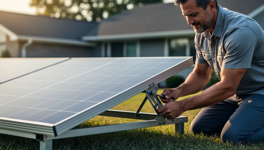
Connect your solar panel frame directly to a grounding rod using 6-gauge bare copper wire and listed grounding lugs—this single action protects your system from lightning strikes and prevents dangerous electrical shocks. Strip back half an inch of wire, insert it into the grounding lug attached to your panel’s frame hole, and torque it to manufacturer specifications, typically 50 inch-pounds for most residential modules.
Drive an 8-foot copper-clad grounding rod into the earth near your array until only 4-6 inches remain above ground, then clamp your ground wire securely using an approved acorn clamp. This creates the essential earth connection that channels fault currents and lightning safely into the ground, away from your home and equipment.
Verify continuity between all panel frames using a multimeter set to resistance mode—you should see less than 0.5 ohms between any two grounded components. This confirms your grounding system forms one unified protective network rather than isolated islands that leave gaps in your safety coverage.
I learned this the hard way during my first DIY installation when I assumed the racking system automatically grounded everything. After a summer thunderstorm, I discovered several panels had intermittent connections due to paint and anodization blocking metal-to-metal contact. Now I always use star washers and grounding washers that bite through protective coatings to ensure reliable electrical bonds.
Proper grounding isn’t just about following electrical code—it’s about protecting your investment and your family. Whether you’re installing a small off-grid cabin system or a full rooftop array, understanding these grounding fundamentals gives you the confidence to build safely and sleep soundly, knowing your solar installation can handle whatever Mother Nature throws at it.
What Solar Module Grounding Actually Means (In Plain English)
Proper grounding clips create secure metal-to-metal contact with solar panel frames, essential for safety and code compliance.
The Lightning Rod Principle
Think of grounding like a lightning rod on a barn—it’s not there to attract lightning, but to give it a safe escape route if it does strike. Your solar array works the same way. When I first installed my panels, my neighbor Charles asked why we needed all those grounding wires. I told him: imagine electricity is like water flowing through pipes. Most of the time, it flows exactly where you want it to go. But what happens during a lightning strike or electrical fault? Without grounding, that surge has nowhere to go except through your expensive equipment or, worse, through you.
Grounding creates a dedicated pathway—the path of least resistance—that directs excess electricity safely into the earth. It’s your system’s emergency exit. When lightning strikes nearby or a wire comes loose, that electricity follows your grounding conductor straight into the ground rather than frying your inverter, charge controller, or batteries.
This isn’t just about protecting gear. It’s about protecting people. A properly grounded system ensures that if something goes wrong, the excess current trips your breakers or blows fuses instead of creating dangerous voltage on metal frames you might touch. It’s simple physics working as your invisible safety net.
Grounding vs. Bonding: They’re Different (And You Need Both)
Here’s something I learned the hard way during my first solar installation: I kept hearing “grounding” and “bonding” used interchangeably, and I figured they were basically the same thing. Spoiler alert: they’re not, and understanding the difference might just save your system.
Think of it this way: grounding is about creating a path to the earth itself. It’s like giving excess electricity a safe escape route during a lightning strike or fault. You’re literally connecting your system to a grounding rod driven into the ground or to your home’s existing grounding system.
Bonding, on the other hand, is about connecting all the metal parts of your solar array together so they’re at the same electrical potential. Picture holding hands in a circle with your friends – everyone’s connected. In your solar setup, this means connecting all the aluminum frames, mounting rails, and metal enclosures together with bare copper wire.
Here’s why you need both: bonding prevents dangerous voltage differences between metal parts you might touch. Grounding gives fault currents somewhere safe to go. Without bonding, you could get shocked touching two different metal parts. Without grounding, your equipment has no protection from surges.
The good news? Most grounding kits include components for both. Just remember: bonding connects metal to metal, grounding connects metal to earth.
Why Skipping Grounding Is a Terrible Idea
The Safety Risks You’re Taking
Let me share something that happened to a friend of mine last summer. Jake installed a small solar array on his shed—everything looked great until a thunderstorm rolled through. A nearby lightning strike sent a surge through his system, frying his charge controller and nearly starting a fire in his battery bank. The culprit? No proper grounding path for that electrical energy to safely dissipate into the earth.
When solar panels aren’t grounded correctly, you’re essentially creating pathways for electricity to go wherever it wants—and trust me, you don’t want to be part of that circuit. Ungrounded systems can deliver serious shocks, especially in wet conditions or when metal frames become energized through wiring faults. I’ve heard stories of folks getting knocked back just touching their panel frames during maintenance.
Fire risks are real too. Without proper grounding, electrical faults can create arcing, which generates intense heat. Combined with the combustible materials often found near solar installations—wooden roofs, dried leaves, insulation—you’ve got a recipe for disaster.
Lightning damage extends beyond direct strikes. Even nearby strikes create voltage surges that travel through your system, damaging inverters, batteries, and sensitive electronics. A proper ground connection gives this energy a safe path to earth, protecting your investment and, more importantly, your home and family.
How Bad Grounding Destroys Expensive Equipment
Poor grounding isn’t just a minor oversight—it’s a fast track to destroying your solar investment. Here’s what happens: without proper grounding, voltage surges from lightning strikes or grid fluctuations have nowhere safe to go. Instead, they travel straight through your system, frying sensitive electronics in milliseconds. I learned this the hard way when a neighbor lost a $2,000 inverter during a summer storm because he’d skipped the grounding wire to save twenty bucks.
Static electricity buildup is equally destructive but sneakier. Over time, charge accumulates on ungrounded panels and metal frames. Eventually, it discharges—sometimes into your charge controller or inverter’s delicate circuitry. The result? Burnt circuit boards, damaged capacitors, and equipment that suddenly stops working for no apparent reason.
Even the solar panels themselves aren’t immune. Voltage imbalances can create hot spots that degrade panel efficiency or crack the photovoltaic cells. Protecting your equipment through proper grounding is genuinely the cheapest insurance you’ll ever buy for your solar setup.
Code Compliance (Yes, It Matters Even for DIY)
Look, I get it—you’re installing solar panels yourself to save money and learn something new, not to wade through building codes. But here’s the reality: proper grounding isn’t just about safety; it’s about protecting your investment. The National Electrical Code (NEC) sets specific requirements for solar installations, including detailed grounding standards. Following these rules matters more than you might think.
When I helped my neighbor troubleshoot his off-grid setup, we discovered his homeowner’s insurance had a clause that could deny claims for non-compliant electrical work. That’s a sobering thought when you’ve got $10,000 worth of panels on your roof. Proper code compliance and inspection documentation protects you if something goes wrong.
Beyond insurance, code-compliant installations preserve your home’s value. Future buyers (and their inspectors) will scrutinize your solar setup. Non-compliant work can torpedo a sale or force expensive corrections later. The good news? NEC grounding requirements are straightforward once you understand them, and following them ensures your system is both safe and legitimate.
The Essential Components for Solar Module Grounding
Grounding Clips and Lugs: Your Connection Points
Getting your panels properly grounded starts with choosing the right connection hardware. Think of grounding clips and lugs as the handshake between your solar module frames and the grounding system—they need to fit perfectly to work safely.
Most solar panels come with aluminum frames, and you’ll need grounding clips specifically designed to match your frame’s profile. I learned this the hard way on my first installation when I bought generic clips that didn’t quite seat properly. The different frame manufacturers have varying depths and widths, so always check your panel specifications first.
You’ll typically encounter two main types: module bonding clips (which connect multiple panels together in a grounded array) and grounding lugs (which connect your grounding wire to the frame). Module bonding clips usually have teeth or serrated edges that bite through any oxidation on the aluminum to create solid metal-to-metal contact. Some newer designs use spring-loaded mechanisms that are easier to install and remove if you need to service your array.
When shopping, look for clips rated for outdoor use and made from corrosion-resistant materials like stainless steel. They should be listed or certified for grounding purposes—this isn’t the place to save a few dollars with generic hardware. Most quality clips will specify which frame profiles they’re compatible with, making your selection process straightforward. For a typical residential installation, you’ll need one clip per panel corner where frames meet, plus lugs wherever you’re connecting grounding conductors.
Grounding Wire and Cable Sizing
Choosing the right grounding wire might seem like a small detail, but trust me, it makes a huge difference in your system’s safety and longevity. I learned this the hard way during my first installation when I thought any old wire would do – thankfully, a friend who’s an electrician stopped by and set me straight before I energized the system.
For solar grounding, copper wire is your best friend. It’s the standard for good reason: excellent conductivity, corrosion resistance, and code compliance. The gauge size depends on your system scale. For most residential setups under 10 panels, a 6 AWG copper wire handles grounding conductor duties beautifully. Smaller systems (just a few panels) can sometimes use 8 AWG, while larger installations might require 4 AWG or even 2 AWG. Check your local codes, but these are solid starting points.
Now, bare versus insulated wire – this trips up many DIYers. Bare copper works great for equipment grounding conductors running from panel frames to ground rods, and it’s often more affordable. However, insulated wire (usually green or green with yellow stripe) protects against accidental contact and works better in conduit or areas where the wire might touch other materials. I generally use bare wire for direct burial to ground rods and insulated for everything else. It’s worth the small extra cost for peace of mind and easier inspection approval.
Ground Rods, Grounding Electrodes, and Earth Connection
Getting your solar array connected to the earth is the final piece of the grounding puzzle, and you’ve got a couple of solid options depending on your situation.
If you’re installing solar panels on a building that already has a proper grounding system, you’re in luck. You can connect your solar array’s grounding conductor to the existing ground rod or grounding electrode system at your main electrical panel. This is often the simplest approach, especially for rooftop installations. Just make sure that existing ground is up to code and in good condition. I learned this the hard way on my first installation when Charles pointed out that my 30-year-old ground rod connection was corroded beyond usefulness.
For standalone systems or new installations, you’ll need to drive a ground rod into the earth. The standard is an 8-foot copper-clad steel rod, though some jurisdictions require 10-foot rods depending on soil conditions. The rod needs to be driven vertically into the ground until only about 4-6 inches remain above the surface. Rocky soil can make this challenging, so having a sledgehammer and plenty of patience helps. If you absolutely can’t get the rod deep enough vertically, you can bury it horizontally in a trench at least 30 inches deep, though vertical is always preferred.
Multiple ground rods spaced at least 6 feet apart provide even better grounding, particularly in sandy or rocky soil where resistance might be higher. Connect your equipment grounding conductor to the rod using an approved grounding clamp, ensuring the connection is tight and weather-resistant.
How to Ground Your Solar Modules: Step-by-Step
Step 1: Plan Your Grounding System Layout
Before you grab your tools and start connecting wires, take a moment to sketch out your grounding plan. I learned this the hard way on my first installation when I realized halfway through that I’d positioned my grounding components in spots that made connections unnecessarily complicated.
Start by creating a simple diagram of your solar array layout. Mark each panel’s location and identify where your frames will connect. Most importantly, trace the path your grounding conductor will take from your array all the way to your grounding electrode (usually a grounding rod driven into the earth near your home’s main electrical panel).
Next, pull out those manufacturer specifications that came with your panels. This step is crucial because not all solar modules ground the same way. Some frames have dedicated grounding lugs, while others require special grounding clips. The spec sheets will tell you exactly where and how to attach your grounding equipment. I keep mine in a weatherproof folder right in my garage for easy reference.
Identify all the bonding points where metal components need electrical connection. This includes panel-to-panel frame connections, the mounting rail system, and any metal junction boxes. Each connection point is an opportunity to create a continuous electrical path that protects your investment and keeps you safe.
A properly grounded solar array includes visible grounding conductors connecting all panel frames to the home’s grounding system.
Step 2: Install Grounding Clips on Panel Frames
Now comes the hands-on part where you’ll attach those grounding clips to your solar panel frames. This is where I learned a valuable lesson during my first installation: placement really matters. You want to position each clip on the panel frame where it will make solid contact with your grounding wire, typically along the long side of the frame about one-third of the way from either end.
Before snapping the clip on, take a second to inspect the frame. If there’s any anodization, paint, or oxidation where the clip teeth will bite, give it a quick scrub with a wire brush or some fine-grit sandpaper. I know it seems tedious, but that metal-to-metal contact is what actually conducts electricity to ground. The grounding clip has sharp teeth designed to penetrate the frame’s surface, but helping it along ensures a better connection.
When you attach the clip, you should hear a satisfying click as it locks onto the frame. Give it a gentle tug to make sure it’s secure. The clip shouldn’t wiggle or slide along the frame.
Here’s a mistake I see all the time: people install clips on powder-coated sections of the frame without removing the coating first. That coating acts as an insulator, defeating the whole purpose of grounding. Also, avoid placing clips near corners or bends where the frame might be weakened. Stick to flat, solid sections of the frame for the most reliable connection and easiest installation.
Step 3: Run Your Grounding Conductor
Now comes the fun part – actually running your grounding conductor through your solar array. Think of this like creating a safety net that connects all your panels together.
Start at the point furthest from your grounding connection point, typically at one end of your array. You’ll route your bare copper wire along the mounting rails, connecting it to each grounding lug or clip as you go. The wire should follow a logical path – I usually run mine along the bottom rail where it’s protected from the elements and out of the way.
When I installed my first array, I learned the hard way that zip-tying the conductor every few feet prevents sagging and potential damage. Use UV-resistant cable ties designed for outdoor use, and don’t cinch them so tight that you damage the wire. Leave just a little slack between connection points to account for thermal expansion.
At each module, make sure your grounding clip firmly contacts both the module frame and your conductor wire. You should feel resistance when attaching clips – if they slide on too easily, they might not be making proper contact. Route the wire through any provided cable management channels in your racking system, keeping it away from sharp edges that could nick the copper.
Where your conductor passes through roof penetrations or conduit entries, add protective grommets or bushings to prevent abrasion. Your grounding wire is only effective if it maintains its integrity over decades of service.
Ground rods driven at least 8 feet into the earth provide the essential connection between your solar system and the earth’s grounding potential.
Step 4: Connect to Your Grounding Electrode System
Now comes the exciting part where everything connects to actual earth! You’ve got a few options here, and I’ll walk you through both scenarios you’re likely to encounter.
If you’re installing a dedicated ground rod, you’ll need to drive it at least 8 feet into the earth (most codes require this minimum depth). Use a ground rod clamp to attach your grounding conductor to the rod. These clamps are specifically designed to create a solid, corrosion-resistant connection. I remember Charles telling me about his first installation where he tried using a regular hose clamp, and let’s just say the inspector wasn’t amused! Save yourself the trouble and get the proper acme threaded clamp or bronze ground rod clamp from your electrical supply store.
For those connecting to an existing building ground, locate your main electrical panel’s grounding bus bar or the ground rod connected to it. You’ll attach your solar system’s grounding conductor here using an appropriate lug or clamp. Make sure all metal surfaces are clean and free of paint or corrosion before making the connection. This ensures maximum conductivity between your solar array and the earth.
In either case, use a torque wrench to tighten connections to manufacturer specifications. Too loose means poor conductivity; too tight can damage threads or conductors. Always verify your connection is below 25 ohms resistance using a ground resistance tester for optimal protection.
Special Grounding Considerations for Different Installations
RV and Van Solar Grounding
Grounding your RV or van solar system presents unique challenges that differ from rooftop installations. I learned this firsthand during my first camper van conversion when I realized mobile setups need special attention to stay safe and code-compliant.
The big question is whether to ground your system to the vehicle chassis or keep it isolated. For most RVs and vans, an isolated system is actually the safer choice. This means your solar panels and charge controller aren’t connected to the metal body of your vehicle. Why? Because vehicles already have their own 12-volt negative grounding system, and mixing that with your solar system’s grounding can create ground loops and potential safety issues.
If you’re running a completely off-grid system with an inverter, check your equipment specifications carefully. Many modern inverters designed for mobile use have built-in isolation features. However, if your system does require chassis grounding, use a properly sized grounding wire connected to a dedicated grounding point on your vehicle’s frame, not just any random bolt.
Remember, mounting hardware should still be isolated from the panels themselves using appropriate standoffs. This prevents accidental grounding through the vehicle body and keeps your system running safely down the road.
Ground-Mount and Pole-Mount Arrays
When your solar array isn’t attached to a building, the grounding approach changes significantly. Ground-mount and pole-mount systems need their own dedicated grounding path since they can’t rely on a building’s existing electrical system.
Here’s what makes these setups different: you’ll need to install separate ground rods near your array. Most electrical codes require at least two ground rods driven eight feet into the earth, spaced at least six feet apart. These rods create a direct path for fault currents and lightning strikes to dissipate safely into the ground.
I learned this the hard way during my first ground-mount installation. I thought I could run a wire all the way back to my house’s grounding system, but my inspector quickly pointed out that the distance made this impractical and potentially dangerous. The standalone ground rod system was actually simpler to install.
Connect your array frame to these ground rods using copper grounding wire, typically 6 AWG or larger depending on your system size. The wire should run in a continuous path from the mounting structure to the ground rods, secured with approved clamps. You’ll also want to install an equipment grounding conductor back to your inverter or combiner box, creating a complete protective circuit. This dual approach protects both your equipment and anyone who might come into contact with the array.
Off-Grid Cabin and Remote Installations
Off-grid installations present unique grounding challenges since you don’t have a utility service ground to connect to. Here’s what you need to know. When I helped my neighbor Charles set up his hunting cabin solar system last year, we learned this firsthand. Without existing electrical infrastructure, you’ll need to create your own grounding electrode system from scratch.
The most reliable approach involves driving an 8-foot copper or galvanized ground rod at least 8 feet into the earth near your solar array or battery bank. If you’re in rocky soil like we encountered, you might need two rods spaced at least 6 feet apart, bonded together with copper wire. For off-grid solar applications, this grounding rod serves as your system’s main reference point to earth.
Connect your charge controller chassis, inverter ground terminal, and equipment grounding conductor to this rod using proper ground clamps. Test resistance with a ground resistance meter if possible, aiming for under 25 ohms. In extremely dry or sandy locations, consider using longer rods or adding bentonite clay around them to improve conductivity.
Common Grounding Mistakes (And How I’ve Made Them)
I’ll be straight with you: I’ve made my share of grounding mistakes over the years, and each one taught me something valuable. Let me share a few doozies so you can learn from my fumbles rather than repeating them.
My most embarrassing mistake happened during my second solar installation. I was so focused on getting the panels mounted perfectly that I completely forgot to check the continuity of my grounding wire before connecting everything. Turns out, I’d accidentally nicked the wire while drilling through my roof, and it wasn’t making proper electrical contact. I only discovered this during the final inspection when my multimeter showed no continuity between the array and ground. The fix was simple, but I had to redo half the installation. Now, I test continuity at every connection point as I go, not just at the end.
Another classic blunder: using the wrong size grounding wire. I thought I could save a few bucks by using slightly thinner wire than recommended. Big mistake. During a lightning storm, the wire couldn’t handle the surge properly, and while nothing catastrophic happened, it did char the connection point. I learned that grounding wire sizing isn’t a suggestion, it’s based on real electrical engineering principles. Always follow the National Electrical Code requirements for your specific setup.
Here’s a sneaky one that caught me off guard: loose connections. I hand-tightened a grounding lug because I couldn’t find my wrench, thinking I’d come back to it later. You can guess what happened. I forgot about it completely. Months later, I was troubleshooting some strange voltage readings and discovered that loose connection had created intermittent grounding. Now I keep a dedicated tool bag for grounding work and never leave a connection until it’s properly torqued.
The lesson from all these mishaps? Take grounding seriously, work methodically, and never rush through the process.
Testing Your Grounding System
Once you’ve got everything connected, it’s time to verify that your grounding system is actually doing its job. Think of this as your safety check before you flip the switch. I learned this lesson the hard way when I skipped testing on my first small project, only to discover months later that a corroded connection had compromised the entire system. Don’t be like early-days Charles!
Start with a visual inspection. Walk along your entire grounding path and look for obvious issues. Check that all connections are tight and secure. Look for signs of corrosion, especially at connection points. Make sure your grounding wire hasn’t been damaged, pinched, or exposed to wear. If you spot green or white crusty buildup around copper connections, that’s corrosion, and it needs addressing.
Next, grab a multimeter and set it to continuity mode (it usually looks like a sound wave symbol). This simple tool becomes your best friend for verifying connections. Touch one probe to your solar panel frame and the other to your grounding electrode or rod. You should hear a beep, indicating a complete electrical path. No beep? Time to check your connections. Test each panel individually if you have multiple modules.
For more thorough testing, switch your multimeter to resistance mode. A properly grounded system should show very low resistance, typically less than 5 ohms between any panel frame and the ground rod. Higher readings suggest loose connections or corroded components that need attention.
Remember, proper testing is part of troubleshooting solar issues before they become safety hazards. Retest your grounding system annually, especially after severe weather, to ensure ongoing protection.
Simple continuity testing with a multimeter verifies that your grounding system is properly connected and functional.
Grounding your solar modules might seem intimidating at first, but here’s the truth: if you’ve made it this far in planning your DIY solar system, you absolutely have what it takes to do this safely and correctly. Proper grounding isn’t just another box to check—it’s your protection against electrical hazards, lightning damage, and equipment failure. More importantly, it’s what stands between you and potential danger when something unexpected happens.
The steps we’ve covered aren’t complicated once you break them down. You’re connecting a few wires, installing some clamps, and driving a grounding rod into the earth. With the right tools and a methodical approach, most DIYers complete their grounding setup in an afternoon. Remember, DIY solar safety is always our top priority at Spheral Solar.
Need help sizing your system or calculating wire gauges? Head over to our interactive calculators—they take the guesswork out of the technical details. And if you run into questions along the way, our community forum is full of experienced DIYers who’ve been exactly where you are now.
You’re not just installing solar panels; you’re taking control of your energy future. Ground it right, stay safe, and enjoy the power you’ve created.
How useful was this post?
Click on a star to rate it!
Average rating 0 / 5. Vote count: 0
No votes so far! Be the first to rate this post.
We are sorry that this post was not useful for you!
Let us improve this post!
Tell us how we can improve this post?
charlesnoble
Here at Spheral Solar, I’m a hands-on solar power enthusiast, constantly exploring and experimenting with DIY solutions. I’m dedicated to sharing my discoveries, insights, and even the bumps I hit along the way, all in the pursuit of a more sustainable future.
Why Your DIY Solar System Needs Rapid Shutdown… by Charlesnoble January 13, 2026 Picture this: You’ve just installed your dream solar array, the panels are gleaming in the sun, and you’re ready to flip the switch—then your inspector mentions something about rapid shutdown compliance. If you’re scratching your head wondering what that means and why it matters for your system, you’re not alone.…
Solar-Powered Irrigation Changed How I Water My… by Charlesnoble November 15, 2025 Last summer, I watched my neighbor haul gasoline cans across his property every few days just to keep his garden watered. Meanwhile, my own irrigation system was running silently on pure sunshine, costing me nothing after the initial setup. That’s the beauty of solar-powered irrigation—it transforms water management from a…
Solar Power Your Kitchen While Saving the Planet (And Money) by Charlesnoble February 21, 2026 Calculate your kitchen’s current energy consumption by tracking appliance usage for one week, noting which devices draw the most power—typically refrigerators, dishwashers, and electric stoves account for 60-80% of kitchen energy use. This baseline becomes your roadmap for meaningful change, showing exactly where solar integration or efficiency upgrades will deliver…
Why Your Solar Panels Are Losing 25% Efficiency (And… by Charlesnoble February 4, 2026 Inspect your solar panels monthly for dust, pollen, bird droppings, and mineral deposits that can reduce energy production by 15-25%. A proper cleaning kit eliminates this performance loss without the $150-300 cost of professional cleaning services, paying for itself after just two uses. Choose a kit with three essential components:…
Why Your Solar Watch Needs Different Care Than… by Charlesnoble November 27, 2025 Protect your solar watch investment by exposing the dial to bright light for at least 8 hours monthly, even when fully charged. This prevents the lithium battery from deep discharge, which permanently reduces its lifespan. Position your watch near a window during work hours or wear it outdoors regularly to…
Why Solar-Powered Fountains Are Better Than You… by Charlesnoble April 1, 2026 Picture a garden fountain that runs entirely on sunlight, requiring no electrical outlets, trenching, or monthly power bills. Solar-powered fountains harness photovoltaic technology to circulate water through decorative displays, creating peaceful ambiance while operating completely off-grid. These self-contained systems typically feature a small solar panel connected to a submersible pump,…
Subscribe for handpicked DIY projects, exclusive tips, and giveaways.
Position your solar panels at an angle equal to your latitude for year-round performance, or adjust seasonally by adding 15 degrees in winter and subtracting 15 degrees in summer to capture maximum sunlight during each season’s sun path. Use a simple angle finder app on your smartphone against the back of your panel to verify… Read more: The Right Tilt Angle Can Boost Your Solar Panel Output by 30% (Here’s How to Find It)
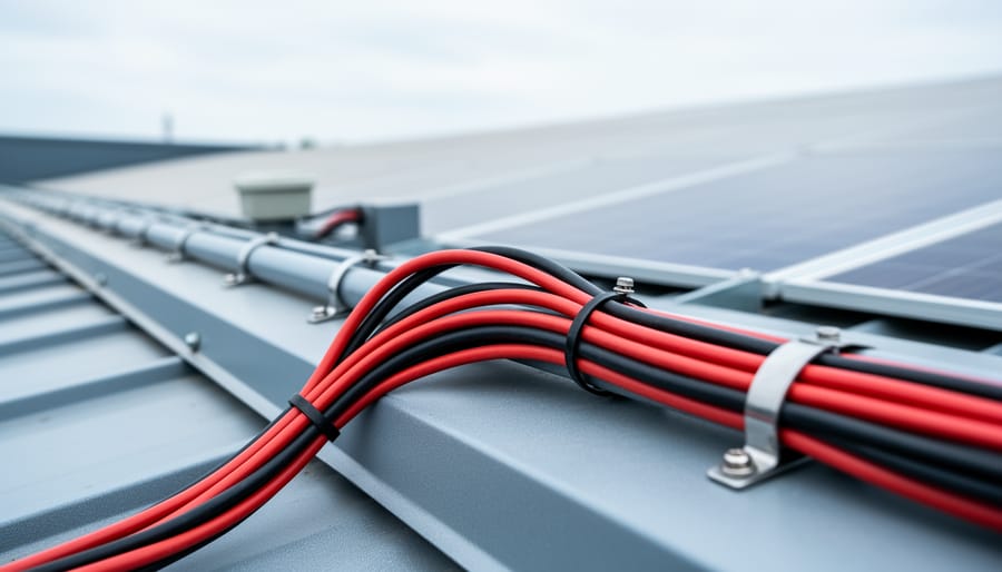
Route your PV wires through UV-resistant conduit within 18 inches of leaving the solar array, securing it every 3 feet with proper clamps to prevent wind damage and code violations. This single step prevents 80% of the wire degradation issues I’ve seen in DIY solar installations over the past decade. Group your positive and negative… Read more: Why Your PV Wire Management Could Fail Inspection (And How to Fix It)
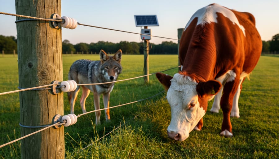
Understand that 6000 volts sounds terrifying but delivers surprisingly low amperage—typically around 120 milliamps for just 3/10,000th of a second per pulse. This combination creates an unforgettable shock that trains animals to avoid the fence without causing lasting harm. The voltage pushes current through thick fur and hide, while the minimal amperage and microsecond duration… Read more: Why 6000 Volts Won’t Kill Your Livestock (But Will Stop Predators Cold)


")
")
")
")

")
")
")
")
")

")