How to Test Your DIY Solar System Like a Pro (Without the Pro Price Tag)
Updated:
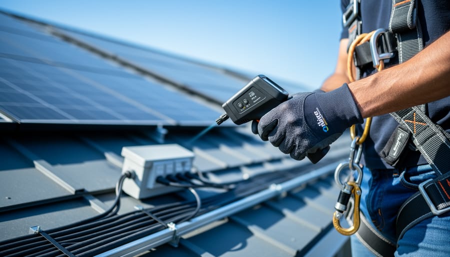
Flip the main DC disconnect three times while monitoring voltage drop—this single action reveals whether your connections can handle full load without dangerous resistance buildup. Check every MC4 connector with an infrared thermometer under peak sun; any reading more than 10 degrees above ambient temperature signals a faulty crimp that could spark a fire next summer. Power up your inverter and let it run for 72 continuous hours while logging performance data every 15 minutes—professional commissioning catches intermittent faults that disappear during quick tests but cost you thousands in lost production over a system’s lifetime.
Solar commissioning is the difference between a system that works today and one that works safely and efficiently for the next 25 years. You’ve already invested serious time and money into your DIY solar installation, but the job isn’t finished when the last panel gets bolted down. The commissioning phase—what professionals call the systematic verification and documentation of system performance—is where amateur installations either prove their worth or reveal expensive mistakes.
I learned this the hard way on my first off-grid cabin project. Everything powered up beautifully on day one. Six months later, I was troubleshooting mysterious power losses that traced back to a single overlooked connection test. That failure cost me a weekend of diagnostic work and a burned charge controller.
The good news? Professional-grade commissioning doesn’t require professional-grade equipment or expertise. With a basic multimeter, an infrared thermometer, and the systematic approach outlined here, you can validate every critical component of your solar system. This process transforms guesswork into certainty, giving you documented proof that your system meets safety standards and performance expectations. You’ll sleep better knowing your installation won’t fail during the first storm or silently underperform for years.
What Solar Commissioning Actually Means (And Why Your DIY System Needs It)
The Difference Between ‘It Works’ and ‘It Works Safely’
Here’s something I learned the hard way during my first major solar installation: just because panels are generating electricity doesn’t mean your system is safe or properly configured. I watched my neighbor’s seemingly functional setup overheat a charge controller because no one had verified the voltage levels were within spec during different weather conditions. It worked fine for three sunny weeks, then failed spectacularly on the first cloudy morning when the system tried to compensate.
Think of it like assembling furniture. You can bolt the pieces together and it’ll stand upright, but if you skipped steps or used the wrong screws, it might collapse when you actually use it. A solar system is similar. Your panels might light up your shed today, but without proper commissioning, you won’t know if the wiring can handle full load on a blazing summer afternoon, or if your grounding will protect you during a thunderstorm.
The reality is that electricity is unforgiving. I’ve seen systems where reversed polarity went unnoticed until someone tried to add a second panel bank. I’ve encountered installations where loose connections created arc flash hazards. The panels were producing power in every case, but the systems were accidents waiting to happen.
Proper commissioning catches these issues before they become dangerous or expensive. It’s the difference between hoping everything works and knowing with confidence that your system will perform safely for decades. That peace of mind is worth the extra effort.
A multimeter testing solar panel connections demonstrates the essential verification step in DIY solar commissioning.
Your Pre-Commissioning Checklist: What to Verify Before Going Live
Visual Inspections That Could Save Your System
Before you even power up your system, a thorough visual inspection can catch issues that might otherwise damage equipment or create safety hazards. Think of it as your first line of defense against costly mistakes.
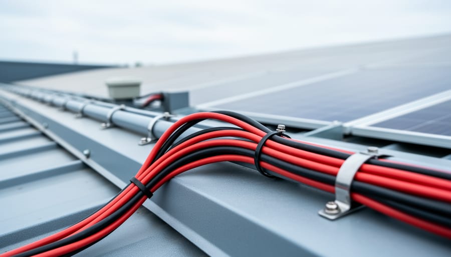
Start with your wiring. Check that all wire gauge matches your system’s requirements—undersized wires are one of the most common DIY mistakes Charles has encountered. Look for any exposed copper at connection points, which indicates stripped wire that’s too long. You want just enough bare wire to make solid contact, nothing more. Also scan for any nicks or cuts in the insulation, especially where wires pass through holes or near sharp edges.
Next, examine all connections carefully. Every MC4 connector should click firmly into place—if it doesn’t, something’s wrong. Proper connector installation means no visible gaps and no wiggle room. Charles once visited a system where loose connectors had created enough resistance to melt the plastic housing. Inside your combiner box and inverter, verify that all terminal screws are tight. Give each wire a gentle tug; it shouldn’t budge.
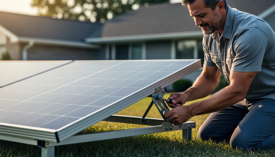
For mounting, check that all bolts are secured and panels sit flat without warping. Uneven mounting can stress panel frames and create microcracks over time. Finally, verify adequate spacing around your inverter for ventilation—overheating is a silent performance killer. Take photos during this inspection; they’re invaluable references if issues arise later.
Double-Checking Your Electrical Work
Before you flip that switch and celebrate, let’s talk about double-checking your electrical work. Think of this as your safety net—the moment where you catch mistakes before they become problems. I learned this lesson the hard way during my second installation when I discovered a loose connection that had been arcing inside a junction box. Not fun.
Start with wire sizing. Your wires need to handle the current flowing through them without overheating. Check your system’s maximum amperage and compare it to the wire gauge you’ve installed. A simple rule: thicker wires (lower gauge numbers) carry more current. If you’re running 30 amps through 10 AWG wire, you’re good. Through 14 AWG? That’s a fire waiting to happen. For detailed guidance on this critical safety aspect, review proper wire sizing and safety practices.
Next, verify polarity everywhere. Your positive wires should connect to positive terminals, negative to negative. This sounds obvious, but reversed polarity can damage inverters and charge controllers instantly. Use a multimeter to confirm—red probe to positive, black to negative. You should see a positive voltage reading. If it’s negative, you’ve got things backwards.
Grounding deserves special attention. Every metal component—panels, racks, junction boxes—should have a dedicated ground wire connecting to your grounding system. Check that green or bare copper wires are securely attached to ground lugs, not just looped around a screw.
Finally, tug test every connection. Seriously, give each wire a firm pull. If anything moves or comes loose, you’ve found a problem before it finds you. Proper connections don’t budge. Tighten terminal screws to manufacturer specifications, typically with a torque screwdriver for critical connections.
Verifying connection tightness on electrical terminals is a critical pre-commissioning safety check.
Essential Tests You Can Actually Do Yourself
Testing Your Solar Panels and Array
Now comes the moment of truth—let’s test those panels! Think of this as a health checkup for your solar array before you bring it fully online. I remember the first time I fired up my panels; I was equal parts excited and nervous. Having the right tools and knowing what to look for made all the difference.
You’ll need a digital multimeter—nothing fancy, a basic model from your local hardware store works perfectly. Make sure it can measure both DC voltage and current, which most can. For larger arrays, a clamp meter can be helpful for measuring current without breaking connections.
Start with the open-circuit voltage test. With your panels disconnected from everything (including the charge controller), measure across the positive and negative terminals in full sunlight. Compare this reading to your solar panel specifications. You should see something close to the listed Voc, typically 30-50 volts for a standard panel. Lower readings might indicate shading, dirty panels, or a problem.
Next, test short-circuit current. This one requires care—briefly connect your multimeter (set to measure DC amps) across the terminals. The reading should approach the rated Isc from your spec sheet. Do this quickly to avoid stressing your meter.
Finally, verify your wiring. For series connections, voltages should add up. For parallel connections, current should add up while voltage stays constant. Walk through each connection point, checking polarity with your multimeter. Reversed polarity won’t just prevent your system from working—it can damage equipment. Taking these measurements now saves headaches later and gives you confidence your array is ready for prime time.
A properly installed charge controller with clear display readings is ready for commissioning tests.
Charge Controller Commissioning Tests
Your charge controller is the brain of your solar setup, so testing it properly is crucial. Think of this as teaching your system’s traffic cop to direct power where it needs to go. I learned this the hard way when my first DIY system kept overcharging batteries because I skipped proper controller verification.
Start by checking your controller settings match your battery type. Most controllers have settings for flooded, AGM, or lithium batteries, and using the wrong profile can damage your batteries or reduce their lifespan. Double-check the absorption voltage, float voltage, and equalization settings against your battery manufacturer’s specs. Write these numbers down before you start, it makes verification much easier.
Next, test voltage regulation by monitoring how the controller responds throughout a sunny day. Watch as your panels produce power and the controller adjusts charging stages from bulk to absorption to float. A multimeter is your best friend here. Measure the voltage at the battery terminals and confirm it matches what the controller display shows, within 0.2 volts. If there’s a bigger difference, you might have connection issues.
Simulate different conditions if possible. Cover your panels partially to see how the controller handles reduced input, then uncover them to watch it ramp up. This real-world testing reveals whether your controller truly understands what’s happening.
Finally, verify the controller’s low-voltage disconnect works by checking when it cuts power to protect your batteries from over-discharge. This safety feature could save your entire battery bank from permanent damage.
Battery Bank Testing and Safety Checks
Battery testing deserves your full attention because safety comes first, always. Before touching anything, verify your battery bank is configured correctly by checking that all cells are connected in the right series and parallel arrangement. Grab your multimeter and measure the total voltage across the entire bank. It should match your system voltage, whether that’s 12V, 24V, or 48V. If you’re seeing odd readings, stop and double-check your connections.
I remember Charles once found a battery bank reading 36V when it should have been 48V. Turned out one battery wasn’t making contact. Simple fix, but it would have caused serious headaches down the line.
Test individual battery voltages too. For battery system basics, each cell or module should read within 0.1V of its neighbors. Larger discrepancies suggest imbalance issues that need addressing before regular operation.
Check all terminal connections with a gentle tug test. Loose connections create resistance, heat, and potential fire hazards. Torque them to manufacturer specifications using a torque wrench.
Finally, verify your battery management system is communicating properly with your charge controller. This safeguard prevents overcharging and deep discharge, protecting both your investment and your home.
Inverter Function and Load Testing
Now comes the exciting part—making sure your inverter actually works as intended! Start by verifying the inverter’s output voltage and frequency with a multimeter. Most grid-tie inverters should output 120V or 240V AC at 60Hz (or 50Hz depending on your location). Compare these readings to your inverter’s specifications.
Next, test with actual loads rather than just measuring empty circuits. I learned this lesson when Charles once told me about a system that tested perfectly with no load but stumbled under real-world conditions. Start small—plug in a lamp or phone charger—then gradually increase to heavier loads like a microwave or power tools. Watch for voltage drops or unusual inverter behavior.
The shutdown and startup sequences are critical safety features. Test your inverter’s automatic shutdown by simulating a grid failure (if it’s grid-tied) or disconnecting the solar input. It should shut down cleanly within seconds. Then verify it restarts smoothly when conditions normalize. For battery-based systems, test the low-voltage disconnect to ensure your batteries are protected.
Document each test with photos and notes. This creates a baseline for future troubleshooting and gives you confidence that your system will perform reliably when you need it most.
The Tools You’ll Need (Most of Which You Probably Already Have)
Here’s the good news: you probably won’t need to raid your retirement fund to properly commission your solar system. When I first started testing my panels, I thought I’d need thousands of dollars in specialized equipment. Turns out, a few hundred bucks and some creativity got me professional-grade results.
Let’s start with the absolute essentials. A quality multimeter is your best friend here, and I’m talking about something in the $40-80 range, not a $5 bargain bin special. You’ll use this constantly to verify voltage, current, and continuity throughout your system. Look for one that can handle at least 600V DC and has a decent amperage range. Mine is a simple Fluke model that’s survived five years of amateur abuse.
For measuring panel performance, a solar irradiance meter helps you verify actual versus expected output. Professional pyranometers cost thousands, but smartphone apps paired with a $30 light meter give surprisingly accurate readings for our purposes. They help you confirm whether your panels are producing what they should based on available sunlight.
A clamp meter becomes invaluable when you’re checking current without breaking circuits. The affordable ones (around $50) work great for verifying that strings are balanced and producing similar currents under identical conditions.
Don’t forget the humble infrared thermometer, usually under $30. Hot spots in connections, combiner boxes, or panels themselves tell you stories about loose connections or failing components before they become expensive problems.
You’ll also want basic hand tools: insulated screwdrivers, wire strippers, and zip ties for securing test leads. A notebook or smartphone for documenting readings is essential because trust me, you won’t remember that voltage reading from panel three when you’re testing panel twelve.
The interactive calculator I’ve built into this guide helps you determine which measurements matter most for your specific system size and configuration, so you’re not wasting time on unnecessary tests.
Creating Your Own Commissioning Documentation
When I first set up my backyard solar array, I made a classic mistake—I didn’t write anything down. Six months later, when performance seemed off, I had no baseline measurements to compare against. I learned the hard way that documentation isn’t bureaucratic busywork; it’s your future self’s best friend.
Think of commissioning documentation as creating a “birth certificate” for your solar system. You’re recording how everything should work when it’s healthy, which makes spotting problems later incredibly straightforward. More importantly, if you decide to expand your system or troubleshoot issues years down the road, you’ll have concrete data instead of fuzzy memories.
Start with the basics: record your system’s specifications, including panel wattage, inverter model, battery capacity, and wiring gauge. Take photos of your complete setup from multiple angles—these visual references are gold when you’re scratching your head about how something was originally connected.
Next, document your baseline performance measurements. Record open-circuit voltage and short-circuit current for each string, battery charge and discharge rates, inverter efficiency readings, and power output at different times of day. Your monitoring system setup might track some of this automatically, but manual measurements during commissioning provide critical verification points.
For templates, keep it simple. A spreadsheet works perfectly—create columns for date, measurement type, expected value, actual value, and notes. Some folks prefer a physical notebook they can take to the roof. Whatever method you choose, make it easy to update and reference.
Consider creating a troubleshooting timeline section where you note any issues, changes, or maintenance. This running log becomes invaluable for identifying patterns and understanding your system’s personality over time.
Documenting test results and baseline measurements creates a valuable reference for future troubleshooting.
When to Call in a Professional (Yes, Sometimes You Should)
Look, I love a good DIY challenge as much as anyone, but here’s the truth: some parts of solar commissioning really do need a pro. And that’s okay. Knowing when to call for backup is actually a sign of a skilled DIYer, not a weakness.
First up: utility interconnection. Most utilities require their own inspection and formal approval before connecting your system to the grid. This isn’t something you can skip or work around. A licensed electrician familiar with local utility requirements can navigate the paperwork minefield and ensure your installation meets their specific standards. Trust me on this one—I once spent three months going back and forth with my utility because I misunderstood one checkbox on their application.
Complex troubleshooting is another area where professionals shine. If you’ve run through all your basic tests and something’s still not right—maybe you’re seeing voltage fluctuations you can’t explain, or your monitoring system shows bizarre power curves—an experienced solar tech with specialized diagnostic equipment can spot issues you might miss.
High-voltage systems above 600 volts definitely warrant professional help. The safety risks multiply quickly at these levels, and most jurisdictions require licensed electricians for this work anyway.
Finally, if your system includes battery storage, especially large-scale lithium systems, consider bringing in someone certified in energy storage systems. Battery commissioning involves thermal management verification and sophisticated charge controller programming that goes beyond basic solar knowledge.
The goal isn’t to do everything yourself—it’s to understand your system completely and know when expert input makes sense.
You’ve made it through the technical specifications, tackled the testing procedures, and now your solar system is humming along beautifully. Here’s the truth I’ve learned from my own commissioning journey: this final validation step is what separates a collection of solar components from a genuinely reliable power system. Those hours you spend methodically checking voltages, verifying connections, and documenting performance aren’t just busywork—they’re your insurance policy against future headaches.
When I commissioned my first DIY system, I’ll admit I was tempted to skip some tests once I saw the inverter displaying power output. I’m glad I didn’t. Proper commissioning caught two loose connections and a panel operating below spec that would have caused problems down the road. The peace of mind that comes from knowing your system is safe, efficient, and ready for years of service is absolutely worth the effort.
The best part? These tests are completely achievable with basic tools and a methodical approach. You don’t need professional certification to commission your system professionally.
Now it’s your turn to share. What did you discover during your commissioning process? What challenges did you face, and how did you overcome them? Drop your experiences and questions in the comments below—this community thrives when we learn from each other’s solar journeys.
How useful was this post?
Click on a star to rate it!
Average rating 0 / 5. Vote count: 0
No votes so far! Be the first to rate this post.
We are sorry that this post was not useful for you!
Let us improve this post!
Tell us how we can improve this post?
charlesnoble
Here at Spheral Solar, I’m a hands-on solar power enthusiast, constantly exploring and experimenting with DIY solutions. I’m dedicated to sharing my discoveries, insights, and even the bumps I hit along the way, all in the pursuit of a more sustainable future.
Why Your Solar Panel Connectors Matter More Than You Think by Charlesnoble March 4, 2026 Choose MC4 connectors for most residential solar installations—they’ve become the industry standard since 2011, offering waterproof reliability and simple snap-together connections that even first-time DIYers can master in minutes. I learned this the hard way when my first solar setup used mismatched connectors that corroded after one rainy season, costing…
Wire Your Solar System Right the First Time (Before… by Charlesnoble March 18, 2026 Sketch your complete solar system on paper before purchasing a single component—mapping the physical distance from your solar panels to the charge controller, then to the battery bank, and finally to your inverter will reveal the exact wire gauges you need and prevent the costly mistake of voltage drop that…
How Solar Monitoring Systems Actually Talk to Each… by Charlesnoble January 22, 2026 Check your solar panel’s data sheet for the communication protocol it supports—most modern systems use Modbus RTU, RS485, or CAN bus, and matching this protocol with your monitoring hardware prevents compatibility headaches before you start. Download the manufacturer’s protocol documentation and verify voltage levels match between your inverter’s output (typically…
Why Series-Parallel Is the Sweet Spot for Small Solar Setups by Charlesnoble December 2, 2025 Connect two panels in series to double your voltage, then wire two of these series pairs in parallel to maintain higher voltage while increasing your amperage—this series-parallel configuration gives you the sweet spot between performance and practicality for most small-scale solar setups. I learned this the hard way during my…
Why Your Solar Setup Needs Both a Charge Controller… by Charlesnoble April 6, 2026 Check the maximum voltage and current ratings first—these determine whether your controller can actually handle your solar panel array without frying itself on the first sunny day. I learned this the hard way when my first DIY system shut down every afternoon because I’d paired 600 watts of panels with…
Why 8 AWG Solar Wire Might Be Wrong for Your System… by Charlesnoble December 29, 2025 Calculate your system’s maximum current first—8 AWG solar wire safely handles 40-55 amps depending on installation conditions, making it the sweet spot for mid-sized solar arrays between 1,200 and 3,000 watts at 12-24 volts. If your panels produce more than 40 amps combined, you need thicker wire; less than 30…
Subscribe for handpicked DIY projects, exclusive tips, and giveaways.
Position your solar panels at an angle equal to your latitude for year-round performance, or adjust seasonally by adding 15 degrees in winter and subtracting 15 degrees in summer to capture maximum sunlight during each season’s sun path. Use a simple angle finder app on your smartphone against the back of your panel to verify… Read more: The Right Tilt Angle Can Boost Your Solar Panel Output by 30% (Here’s How to Find It)
Route your PV wires through UV-resistant conduit within 18 inches of leaving the solar array, securing it every 3 feet with proper clamps to prevent wind damage and code violations. This single step prevents 80% of the wire degradation issues I’ve seen in DIY solar installations over the past decade. Group your positive and negative… Read more: Why Your PV Wire Management Could Fail Inspection (And How to Fix It)
Understand that 6000 volts sounds terrifying but delivers surprisingly low amperage—typically around 120 milliamps for just 3/10,000th of a second per pulse. This combination creates an unforgettable shock that trains animals to avoid the fence without causing lasting harm. The voltage pushes current through thick fur and hide, while the minimal amperage and microsecond duration… Read more: Why 6000 Volts Won’t Kill Your Livestock (But Will Stop Predators Cold)


")
")

")
")

")
")

")
")