Wire Your Solar System Right the First Time (Before It Becomes a Fire Hazard)
Updated:
Sketch your complete solar system on paper before purchasing a single component—mapping the physical distance from your solar panels to the charge controller, then to the battery bank, and finally to your inverter will reveal the exact wire gauges you need and prevent the costly mistake of voltage drop that kills system efficiency. I learned this the hard way during my first installation when I confidently bought 100 feet of 10-gauge wire, only to discover my 30-foot panel-to-controller run required 8-gauge to maintain safe voltage levels.
Identify every protection device your system requires by tracing the current path: a circuit breaker or fuse between panels and charge controller, another between charge controller and battery, and a third between battery and inverter. These aren’t optional upgrades—they’re the difference between a minor fault and a catastrophic fire. Each protection point needs proper amperage rating based on your maximum current, which means calculating your panel output, battery discharge rate, and inverter draw before selecting components.
Mark polarity clearly at every connection point in your diagram using consistent color coding—red for positive, black for negative, and include grounding connections in green. This simple visual practice prevents the reversed polarity connections that destroy charge controllers and inverters instantly, often before you realize what happened.
Calculate voltage drop for each wire segment using the actual distance, wire gauge, and current your system will carry. If your calculations show more than 3% voltage loss on any segment, increase the wire gauge until you’re under that threshold. This mathematical step separates functioning systems from underperforming disappointments that never deliver their rated capacity.
Every connection shown in your diagram represents a potential failure point, so minimize junction boxes and splices wherever possible by using appropriately-sized continuous wire runs.
Why Solar Wiring Diagrams Matter More Than You Think
When I first started tinkering with solar panels in my garage, I thought wiring diagrams were just fancy illustrations for engineers. Boy, was I wrong. A solar wiring diagram is essentially the blueprint for your entire solar system—it shows exactly how your panels, charge controller, batteries, inverter, and safety devices connect together. Think of it like an instruction manual that could save your project from becoming an expensive paperweight or, worse, a fire hazard.
Here’s a misconception I hear all the time: “I’ll just wing it and connect things as I go.” I get it—you’re excited to see those panels generating power. But here’s the reality: without a proper diagram, you’re gambling with your safety and investment. One reversed polarity or incorrectly sized wire can damage expensive equipment or create dangerous conditions. I learned this the hard way when a friend skipped the planning phase and ended up frying a $400 charge controller because he didn’t account for proper fuse placement.
Solar wiring diagrams matter because they serve three critical purposes. First, they keep you safe by showing where protection devices like fuses and circuit breakers need to go. Second, they ensure code compliance—yes, even DIY systems need to meet electrical codes, especially if you ever want to sell your home or get insurance coverage. Third, they become your troubleshooting map when something inevitably goes wrong. Trust me, when your system stops working at 10 PM, you’ll be grateful for that diagram showing exactly where to check connections.
The good news? Creating and understanding these diagrams isn’t rocket science. Once you grasp the basic components and how electricity flows through your system, reading a wiring diagram becomes second nature. It’s like learning to read a recipe—intimidating at first, but empowering once you get the hang of it.
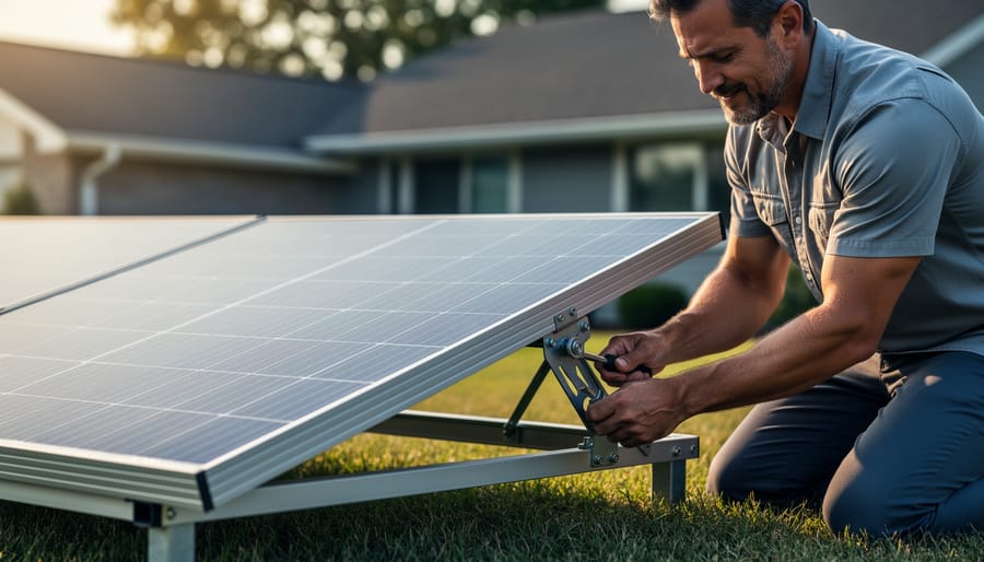
Proper wire gauge selection and protection devices are fundamental to safe solar system installation.
Understanding the Core Components in Your Solar Wiring Diagram
Solar Panels and Array Configuration
In solar wiring diagrams, panels are typically shown as rectangles with a positive (+) and negative (-) terminal. You might also see a diagonal line or small circles inside the rectangle, representing the photovoltaic cells. Understanding how these symbols connect is crucial for building an efficient system.
When I first started mapping out my solar setup, the difference between series vs. parallel connections seemed confusing, but it’s actually straightforward. Series connections link the positive of one panel to the negative of the next, increasing voltage while keeping amperage the same. In diagrams, you’ll see a line running from one panel’s + terminal to the next panel’s – terminal. Parallel connections, on the other hand, join all positive terminals together and all negative terminals together, boosting amperage while voltage stays constant.
Your choice depends on your system voltage requirements and the solar panel specifications you’re working with. Most residential systems use a combination approach to balance voltage and current. Pay close attention to these connection patterns in diagrams, as they directly affect your charge controller compatibility and overall system performance.
Charge Controllers: The Traffic Cops of Your System
Think of your charge controller as the traffic cop standing between your solar panels and batteries, making sure power flows safely and efficiently. In your wiring diagram, this component sits right in the middle of the action, and getting its placement right is crucial.
On your diagram, you’ll always show the charge controller receiving input from your solar array and sending regulated output to your battery bank. The controller prevents overcharging during sunny days and stops reverse current drain at night when your panels aren’t producing power.
Here’s where it gets interesting: you’ll encounter two main types. PWM (Pulse Width Modulation) controllers are simpler and cheaper, perfect for smaller systems. I remember Charles mentioning his first off-grid cabin setup used a basic PWM controller that worked beautifully for years. MPPT (Maximum Power Point Tracking) controllers are the upgraded version, squeezing 20-30% more power from your panels by converting excess voltage into usable current. They cost more but pay off in larger systems.
When drawing your diagram, mark your charge controller’s connection points clearly: positive and negative terminals for both the solar input side and battery output side. Many controllers also include load terminals for connecting devices directly, which should be labeled separately. This clarity prevents crossed wires that could damage your entire system.
Battery Banks and Their Connections
In solar wiring diagrams, batteries are typically shown as rectangular boxes with positive and negative terminals marked. You’ll often see them drawn in series (connecting positive to negative terminals to increase voltage) or parallel (connecting positive to positive and negative to negative to increase capacity). Understanding proper battery configuration is essential for system safety and performance.
One common mistake I’ve seen from Charles’s experience is connecting batteries of different ages or capacities together. This creates imbalanced charging and can significantly reduce your battery bank’s lifespan. Another frequent error is forgetting to include proper fusing between the battery and inverter connection, which appears as a small rectangular symbol on diagrams but plays a critical role in fire prevention.
When reading battery symbols, look for capacity ratings (usually in amp-hours) and voltage specifications noted nearby. Series connections multiply voltage while keeping capacity the same, whereas parallel connections keep voltage constant but add capacity together. Most diagrams will use dashed lines to group battery banks together, helping you visualize which batteries work as a unit.
Inverters and Load Connections
The inverter is where the magic happens—it’s the translator between your solar panels’ DC electricity and the AC power your home appliances need. In your wiring diagram, you’ll typically show the inverter positioned between your charge controller (or battery bank, if you have one) and your main AC load panel. Think of it as the bridge between two electrical worlds.
When I first mapped out my system, I learned the hard way that DC and AC loads need different representations on your diagram. DC loads connect directly to your battery bank or charge controller output—things like DC lighting, fans, or USB charging stations. Draw these with solid lines coming from the DC side. AC loads, on the other hand, flow through the inverter first. These include your regular household appliances, and they should branch off after the inverter in your diagram.
Wire routing matters more than you might think. Show the path your wires will actually take, noting where they’ll pass through walls, conduits, or junction boxes. Label wire gauges clearly—typically heavier gauge (lower number) for the DC side due to higher current, and standard residential gauge for AC loads. Include proper grounding symbols throughout, and mark your main disconnect switch between the inverter and load panel. This visual roadmap prevents costly mistakes during installation and helps inspectors understand your system at a glance.
The Critical Protection Devices
When I first looked at a solar wiring diagram, those mysterious boxes labeled “fuse,” “breaker,” and “disconnect” seemed like optional extras. They’re not. They’re the safety heroes that prevent your investment from becoming a fire hazard.
Think of fuses as one-time sacrificial protectors. When too much current flows through your system, the thin metal strip inside melts, breaking the circuit instantly. On diagrams, they appear as small rectangular boxes, usually positioned between your solar panels and charge controller, and again between your battery bank and inverter. They’re represented by a simple symbol showing a wire inside a box.
Circuit breakers serve a similar purpose but can be reset after they trip. You’ll see these depicted as switches with automatic cutoff capability, typically located near battery banks and major loads. I remember the first time my system’s breaker tripped during testing—instead of replacing anything, I just identified the overload issue and flipped it back on.
Disconnect switches are the manual override champions. These allow you to completely isolate different parts of your system for maintenance or emergencies. Diagrams show them as simple switch symbols, and most codes require them between your panels and charge controller, giving you full control when you need it most.
Protection Devices: Your System’s Insurance Policy
Fuses vs. Circuit Breakers: What You Actually Need
When I first started planning my solar system, the fuses versus circuit breakers debate had me scratching my head for days. Here’s what I’ve learned through trial, error, and some helpful advice from the DIY solar community.
Both fuses and circuit breakers protect your system from overcurrent situations that could damage equipment or start fires, but they work differently. Fuses are one-time-use devices with a metal element that melts when too much current flows through. Circuit breakers are reusable switches that trip open when they detect overcurrent, and you can simply reset them.
For most DIY solar systems, I actually recommend circuit breakers. Yes, they cost more upfront—maybe $15-30 versus $5-10 for fuses—but the convenience factor is huge. When you’re testing and troubleshooting your new system (and trust me, you will be), resetting a breaker beats replacing fuses repeatedly. Circuit breakers also give you a convenient disconnect point for maintenance.
That said, fuses have their place. They’re excellent for battery protection in smaller systems because they’re incredibly reliable and fail in a predictable way. Some experienced DIYers use fuses on the battery side and breakers everywhere else.
Sizing is critical for both. Your overcurrent device should be rated at 125% of your maximum expected current. For a 30-amp charge controller, that means a 40-amp breaker. Always round up to the next standard size, and make sure the device is rated for DC voltage—AC-rated devices won’t work safely in solar applications.
Different types of fuses and circuit breakers serve specific protection roles in solar installations.
Sizing Your Protection Devices Correctly
Getting your fuse and breaker ratings right is one of those things that keeps me up at night when I think about DIY solar projects. I’ve seen too many installations where someone threw in whatever breaker they had lying around, and trust me, that’s a recipe for trouble. Let me walk you through the proper way to size these critical protection devices.
The golden rule is simple: your protection device should be rated at 125% of your maximum current, and it must not exceed the ampacity of your wire. Think of it as protecting the weakest link in your chain.
Here’s how to calculate it step by step. First, find your maximum current by dividing your system’s wattage by voltage. For example, if you have a 1,200-watt array on a 12-volt system, that’s 100 amps (1,200 ÷ 12 = 100). Now multiply by 1.25 for the National Electrical Code safety factor: 100 × 1.25 = 125 amps. That’s your minimum breaker rating.
Next, check your wire ampacity. If you’re using 2 AWG wire rated for 115 amps, you’ve got a problem because your 125-amp breaker exceeds the wire’s capacity. You’d need to either upgrade to 1 AWG wire (rated for 130 amps) or reduce your system size.
For a 24-volt system with the same 1,200 watts, the math works better: 1,200 ÷ 24 = 50 amps, times 1.25 = 62.5 amps. Round up to a 70-amp breaker, and you could safely use 6 AWG wire.
When I upgraded my own system last year, I created a simple spreadsheet to test different voltage and wire combinations before buying anything. It saved me from an expensive mistake and gave me confidence that every connection was properly protected.
Where to Place Protection Devices (And Why It Matters)
Getting your protection devices in the right spots is like placing smoke detectors in your home—location absolutely matters. I learned this the hard way during my first installation when I mounted a fuse holder where I couldn’t reach it without a ladder. Not fun when you need to check a blown fuse on a rainy afternoon!
The National Electrical Code (NEC) has specific requirements about where these devices go, and they’re not just being picky. Here’s what you need to know:
At the solar array itself, you need overcurrent protection within 10 feet of where the panels connect together. This protects against current flowing backward into a shaded or damaged panel. Think of it as the first line of defense right at the source.
Between your charge controller and battery bank, place a fuse or circuit breaker as close to the battery as possible—ideally within 7 inches. Batteries can deliver enormous amounts of current if something shorts out, so this placement minimizes the length of unprotected wire that could potentially cause a fire.
Your inverter needs its own dedicated breaker on both the DC input side (near the batteries) and AC output side (where it connects to your breaker panel). These protect both the inverter itself and downstream equipment.
Here’s what happens when placement goes wrong: Protection devices too far from the power source leave sections of wire vulnerable. If a wire gets damaged in that unprotected section, there’s nothing to stop it from overheating or starting a fire. I’ve seen melted wire insulation from this exact mistake—it’s genuinely scary and completely avoidable with proper placement.
Disconnect Switches: Your Emergency Stop Button
Think of disconnect switches as the emergency exit signs of your solar system—they’re there when you absolutely need them. These critical safety devices let you completely shut off power flow, whether you’re doing maintenance, troubleshooting a problem, or responding to an emergency. When I first started working with solar, I learned this lesson quickly: never underestimate the importance of being able to kill power instantly.
In your wiring diagram, disconnect switches typically appear as a simple break symbol in the circuit line, often represented by two parallel lines with a gap between them. You’ll usually need at least two: one DC disconnect between your solar panels and charge controller or inverter, and an AC disconnect between your inverter and your home’s electrical panel. Some jurisdictions require them to be visible and accessible to firefighters—a sobering reminder of why they matter.
The National Electrical Code mandates these disconnects in specific locations, and local codes might add their own requirements. When reading diagrams, you’ll see them clearly marked, often with labels like “PV Disconnect” or “AC Disconnect.” They’re your safety net, plain and simple. Including them properly in your planning isn’t just smart—it’s essential for protecting yourself, your family, and anyone who might need to service your system down the road.
Wire Gauge and Cable Specifications: Don’t Let Your System Choke
Understanding AWG and Why It’s Not Backwards
Here’s something that confused me when I first started designing my solar system: the American Wire Gauge (AWG) system seems to run backwards. Larger numbers actually mean smaller wires! I remember standing in the hardware store, completely baffled that 10 AWG wire was thicker than 12 AWG.
Think of it this way: AWG numbers represent how many times the wire was drawn through a machine to make it thinner. More draws equals a higher number and a skinnier wire. It’s counterintuitive, but once you get it, you’ve got it.
For solar applications, you’ll typically work with these sizes: 10 AWG is common for shorter runs between your charge controller and battery bank, while 8 AWG or even 6 AWG handles longer distances or higher currents. Your solar panels to charge controller connection might use 10 or 12 AWG, depending on the amperage and distance.
The thickness matters because thinner wires create more resistance, which means wasted energy as heat and potential voltage drop. When I upgraded from 12 AWG to 10 AWG on my first system, I immediately noticed better charging performance. Always size up when you’re unsure, because oversized wire is safe, but undersized wire creates dangerous heat and inefficiency.
Understanding wire gauge differences helps prevent voltage drop and ensures system efficiency.
Calculating Wire Size for Your System
Getting the wire size right is crucial for your solar system’s safety and efficiency. I learned this the hard way when my first DIY setup had wires running warm—not a good sign! The key is selecting a proper wire gauge that handles your current without excessive voltage drop.
Here’s a simple approach: You need to know three things—the maximum current your wire will carry (check your panel specs), the distance the wire travels (one way), and what voltage drop you can accept (typically 2-3% is ideal).
The formula considers these factors, but honestly, doing the math manually gets tedious. That’s why we created the Spheral Solar wire size calculator—just plug in your numbers and it tells you exactly which gauge you need. For example, if you’re running 30 amps over 25 feet at 12 volts with a 2% voltage drop target, you’ll need much thicker wire than you might expect.
Remember, undersized wire wastes energy through heat and can create fire hazards, while oversized wire just wastes money. Use the calculator to find that sweet spot for your specific setup.
Special Considerations: UV-Rated, Buried, and Marine Applications
Not all solar installations enjoy the same controlled environment. If you’re mounting panels on your RV, running cables underground to a detached garage, or outfitting a sailboat with solar power, you’ll need specialized cable that can handle those conditions.
UV-rated cable is essential for any wire exposed to direct sunlight. Standard PV wire already has UV protection, but if you’re using flexible cable for portable systems or making custom extensions, verify the jacket is specifically rated for outdoor UV exposure. I learned this the hard way when a friend’s cheap extension cable became brittle and cracked after just one summer season.
Underground installations require direct-burial rated cable, which has a thicker, moisture-resistant jacket. You can’t just bury standard wire, even inside conduit, without risking long-term degradation. Check local electrical codes too, as burial depth requirements vary.
For marine or vehicle applications, look for tinned copper wire rather than bare copper. The tin coating resists corrosion from salt spray and vibration. Also ensure your solar panel connectors match the environmental rating of your cable, since connections are often the first failure point in harsh conditions.
Reading and Creating Your Own Solar Wiring Diagram
Common Symbols and What They Mean
When I first looked at a solar wiring diagram, I felt like I was staring at ancient hieroglyphics. But here’s the thing—once you learn what these symbols mean, everything clicks into place. Think of them as a universal language that electricians and solar enthusiasts use worldwide.
Let’s start with the most common symbols you’ll encounter. Solar panels are typically shown as rectangles with diagonal lines inside, representing the photovoltaic cells catching sunlight. The battery symbol looks just like what you’d expect—a series of short and long parallel lines. Your charge controller appears as a rectangle with connections on both sides, acting as the traffic cop between your panels and batteries.
Now for the safety components. Circuit breakers show up as a small circle with a line through it, sometimes with a zigzag to indicate it can interrupt current flow. Fuses look similar but are usually depicted as a small rectangle with a curved line inside. Ground connections—absolutely critical for safety—appear as three descending horizontal lines getting progressively shorter, like a pyramid.
Wires and connections have their own symbols too. A simple line represents a wire, while a dot where lines intersect means they’re connected. If lines cross without a dot, they’re not touching—just passing by each other.
Here’s my personal tip: print out a symbol reference sheet and keep it handy while studying diagrams. Within a week, you’ll recognize these symbols instantly, making any solar diagram much less intimidating and far more useful for your project planning.
Sketching Your System: A Step-by-Step Approach
Creating your first solar wiring diagram might feel intimidating, but here’s the truth: you don’t need fancy software or an engineering degree to get started. When I designed my first small solar setup for a backyard workshop, I sketched it out on the back of an envelope during lunch. That simple drawing saved me from making some costly mistakes and helped me visualize exactly what I needed before heading to the hardware store.
Start with the basics. Grab a pencil and paper, or if you prefer digital tools, free options like draw.io or even PowerPoint work surprisingly well. Begin by drawing your solar panels at the top of the page. These are your power source, so everything flows from here.
Next, sketch the path your electricity takes. Draw a line from your panels to your charge controller, which regulates the power going to your batteries. From the charge controller, draw lines to your battery bank. Then show the connection from batteries to your inverter, which converts DC power to AC power for household appliances.
Here’s what you absolutely must include: label every component with its specifications. Write down panel wattage, battery voltage and amp-hours, and wire gauge sizes. Mark the location of every fuse and circuit breaker between components. These protective devices are your safety net, so don’t skip them.
Add the distances between components right on your diagram. This helps you calculate proper wire sizes later. Include polarity markings with plus and minus signs to avoid reversed connections.
Don’t worry about making it perfect. Your diagram is a working document that will evolve as you refine your system design. The goal is clarity, not artistic merit.
Real-World Wiring Diagrams for Common DIY Solar Projects
Basic Off-Grid Cabin System
Let me walk you through the most common off-grid setup you’ll encounter—the one I started with in my own workshop before expanding to my whole homestead. This basic system includes four main components: your solar panels, a charge controller, a battery bank, and an inverter.
Here’s how they connect: Your solar panels wire directly to the charge controller’s input terminals. From the charge controller’s output, you run cables to your battery bank—always connecting positive to positive and negative to negative. The charge controller protects your batteries from overcharging during sunny days and prevents reverse current flow at night.
Next, your inverter connects directly to the battery bank. This is where DC power from your batteries converts to AC power for running household appliances. Between your battery and inverter, you’ll need a fuse or breaker rated for your system’s amperage—this is your safety net if something goes wrong.
A typical starter system might use two 100-watt panels, a 30-amp charge controller, a 200-amp-hour battery bank, and a 1000-watt inverter. Remember to size your wire gauge appropriately—most basic systems use 10 AWG wire between components, though shorter runs might handle 12 AWG just fine.
A properly wired off-grid system demonstrates correct component placement and cable routing.
Van or RV Solar Installation
Mobile solar installations come with unique wiring considerations that differ from stationary setups. When I helped my friend Charles install panels on his vintage Airstream, we quickly learned that vehicle movement, grounding, and battery management require special attention in your wiring diagram.
The most crucial difference is grounding. Unlike home systems that ground to earth, your RV or van uses the vehicle chassis as the negative return path. Your wiring diagram must show proper connections to the chassis ground at multiple points, ensuring you’re working with the vehicle’s existing electrical system rather than against it.
Dual battery setups are extremely common in mobile installations. Your diagram should clearly illustrate how your house battery bank stays separate from your starting battery while allowing controlled charging from the alternator. This typically involves a battery isolator or DC-to-DC charger, which prevents your solar setup from draining the battery you need to actually start the engine.
Space constraints mean compact charge controllers and creative panel mounting solutions. Document wire runs carefully in your diagram, noting where cables pass through walls or under flooring. Mobile installations experience vibration and temperature extremes, so your diagram should specify marine-grade tinned copper wire and proper strain relief at connection points.
Include fuse locations for both the solar input and load outputs, positioned as close to the batteries as possible for maximum safety.
Portable Solar Generator Setup
Building a portable solar generator is one of my favorite portable solar projects, and the wiring diagram is refreshingly straightforward compared to permanent installations. I built my first one for weekend camping trips, and it’s become my go-to backup during power outages.
Your basic setup includes four main components: the solar panel, charge controller, battery bank, and inverter. The solar panel connects to the charge controller’s input terminals, which prevents overcharging. From there, the controller’s output connects directly to your 12V battery (I recommend starting with a 100Ah deep-cycle battery for versatility). The battery then feeds into your inverter, which converts DC power to standard 120V AC for regular household devices.
Use 10 AWG wire for connections handling up to 30 amps, with appropriate inline fuses between each component (20A fuse between controller and battery is typical). Add an Anderson connector between your panel and controller for easy setup and breakdown.
Since portability is key, mount everything in a weatherproof container with external solar panel connections. Label all connections clearly—trust me, you’ll thank yourself later when setting up in the dark during an emergency. Include a simple voltmeter to monitor battery levels, helping you avoid damaging over-discharge.
Common Wiring Mistakes That’ll Cost You (And How to Avoid Them)
I’ve made just about every wiring mistake in the book during my early solar experiments, and trust me, learning the hard way is expensive. Let me share the most common errors I see in our community forums so you can skip the frustration and wasted components.
The biggest mistake? Undersizing your wire gauge. I remember when Jake from our community forum excitedly posted about his new 400-watt panel setup. Within a week, he was back online confused about why his wires were getting warm to the touch. Turns out, he’d used 14-gauge wire for a 30-foot run carrying 25 amps. The resistance was creating heat and wasting power. Always calculate voltage drop, especially on longer runs. A good rule of thumb: when in doubt, go one size thicker than you think you need.
Another costly error is mixing up series and parallel connections. Sarah learned this the hard way when she wired four 12-volt panels in series, expecting 12 volts but getting 48 volts instead, which completely fried her 12-volt charge controller. Remember, series connections add voltage while parallel connections add amperage. Double-check your math and your wiring diagram before making that final connection.
Skipping overcurrent protection is like playing Russian roulette with your system. Fuses and breakers aren’t optional decorations. They’re your safety net when something goes wrong. I’ve seen melted wire insulation, scorched junction boxes, and worse because someone thought they could save a few dollars by skipping the fuse.
Then there’s the classic reversed polarity mistake. Positive to negative, negative to positive sounds simple, but when you’re working with multiple connections, it’s surprisingly easy to mix up. Most modern equipment has reverse polarity protection, but not all does. I always use red for positive and black for negative consistently throughout my system, and I test with a multimeter before energizing anything.
Finally, poor connection quality causes more problems than people realize. Loose crimp connections, improper torque on terminals, or mixing dissimilar metals creates resistance, heat, and eventual failure. Invest in proper crimping tools and take your time making solid, weatherproof connections. Your future self will thank you when everything still works perfectly years later.
Getting your solar wiring diagram right isn’t just about connecting dots on paper—it’s about creating a safe, efficient system that’ll serve you for decades. I’ve seen countless projects where folks rushed through the planning stage, eager to flip that switch and start generating power, only to discover dangerous mistakes that required tearing everything apart and starting over. Trust me, taking the extra time upfront saves you headaches, money, and potentially serious safety issues down the road.
Think of your wiring diagram as the blueprint for your energy independence. Just like you wouldn’t build a house without checking the foundation twice, don’t connect your solar system without verifying every connection, fuse rating, and wire gauge. Double-check your calculations, especially when it comes to wire sizing and overcurrent protection. A miscalculation here could mean overheated wires or equipment failure when you least expect it.
Here’s where I encourage you to tap into the incredible resources available at Spheral Solar. Before you make a single connection, use our interactive calculators to verify your component specifications and wire sizing. These tools have helped thousands of DIYers get their systems right the first time, and they’re designed to catch those easy-to-miss details that can make or break your installation.
Even better, join our community forum and share your wiring diagram before energizing your system. Getting feedback from experienced solar enthusiasts who’ve been where you are now is invaluable. They’ll spot potential issues, offer suggestions, and give you the confidence that you’re on the right track. Solar energy is a journey best shared with others who understand the excitement and challenges you’re facing.
How useful was this post?
Click on a star to rate it!
Average rating 0 / 5. Vote count: 0
No votes so far! Be the first to rate this post.
We are sorry that this post was not useful for you!
Let us improve this post!
Tell us how we can improve this post?
charlesnoble
Here at Spheral Solar, I’m a hands-on solar power enthusiast, constantly exploring and experimenting with DIY solutions. I’m dedicated to sharing my discoveries, insights, and even the bumps I hit along the way, all in the pursuit of a more sustainable future.
Why Your Solar Setup Needs Both a Charge Controller… by Charlesnoble April 6, 2026 Check the maximum voltage and current ratings first—these determine whether your controller can actually handle your solar panel array without frying itself on the first sunny day. I learned this the hard way when my first DIY system shut down every afternoon because I’d paired 600 watts of panels with…
Why 8 AWG Solar Wire Might Be Wrong for Your System… by Charlesnoble December 29, 2025 Calculate your system’s maximum current first—8 AWG solar wire safely handles 40-55 amps depending on installation conditions, making it the sweet spot for mid-sized solar arrays between 1,200 and 3,000 watts at 12-24 volts. If your panels produce more than 40 amps combined, you need thicker wire; less than 30…
Why Series-Parallel Is the Sweet Spot for Small Solar Setups by Charlesnoble December 2, 2025 Connect two panels in series to double your voltage, then wire two of these series pairs in parallel to maintain higher voltage while increasing your amperage—this series-parallel configuration gives you the sweet spot between performance and practicality for most small-scale solar setups. I learned this the hard way during my…
Why Lithium-Ion Batteries Changed Everything About… by Charlesnoble December 3, 2025 Match your battery’s voltage to your solar panel system—12V, 24V, or 48V configurations must align perfectly, or you’ll waste energy through conversion losses and potentially damage expensive equipment. Check the battery’s amp-hour (Ah) rating against your daily power consumption: multiply your total watt-hours by 1.2 to account for inefficiency, then…
Why Your Solar Panel Connectors Matter More Than You Think by Charlesnoble March 4, 2026 Choose MC4 connectors for most residential solar installations—they’ve become the industry standard since 2011, offering waterproof reliability and simple snap-together connections that even first-time DIYers can master in minutes. I learned this the hard way when my first solar setup used mismatched connectors that corroded after one rainy season, costing…
How to Test Your DIY Solar System Like a Pro… by Charlesnoble March 19, 2026 Flip the main DC disconnect three times while monitoring voltage drop—this single action reveals whether your connections can handle full load without dangerous resistance buildup. Check every MC4 connector with an infrared thermometer under peak sun; any reading more than 10 degrees above ambient temperature signals a faulty crimp that…
Subscribe for handpicked DIY projects, exclusive tips, and giveaways.
Position your solar panels at an angle equal to your latitude for year-round performance, or adjust seasonally by adding 15 degrees in winter and subtracting 15 degrees in summer to capture maximum sunlight during each season’s sun path. Use a simple angle finder app on your smartphone against the back of your panel to verify… Read more: The Right Tilt Angle Can Boost Your Solar Panel Output by 30% (Here’s How to Find It)
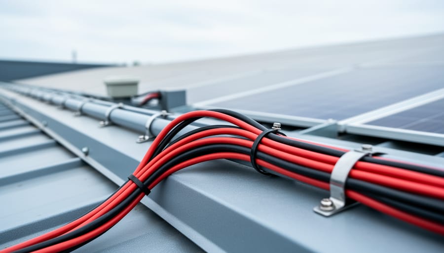
Route your PV wires through UV-resistant conduit within 18 inches of leaving the solar array, securing it every 3 feet with proper clamps to prevent wind damage and code violations. This single step prevents 80% of the wire degradation issues I’ve seen in DIY solar installations over the past decade. Group your positive and negative… Read more: Why Your PV Wire Management Could Fail Inspection (And How to Fix It)
Understand that 6000 volts sounds terrifying but delivers surprisingly low amperage—typically around 120 milliamps for just 3/10,000th of a second per pulse. This combination creates an unforgettable shock that trains animals to avoid the fence without causing lasting harm. The voltage pushes current through thick fur and hide, while the minimal amperage and microsecond duration… Read more: Why 6000 Volts Won’t Kill Your Livestock (But Will Stop Predators Cold)


")
")

")

")
")
")

")

")