Why Your RV Solar Panels Aren’t Charging (And How to Fix Voltage Drops)
Updated:
Check your multimeter readings at each connection point along your solar charging path—from panels to charge controller to battery—to pinpoint exactly where voltage disappears. Most RV solar systems lose 10-30% of their potential power to voltage drop, but this invisible thief often goes undetected until you systematically measure and compare voltages at every junction.
Start by measuring your solar panel output in full sun directly at the panel terminals, then immediately check again at your charge controller input. Any difference greater than 0.5 volts signals trouble in your wiring between these points. I’ve seen countless RV owners blame their panels or controllers when the real culprit was undersized wire running through their roof or corroded MC4 connectors hidden behind access panels.
The most common voltage drops happen at three predictable locations: crimped wire connections that weren’t properly compressed, Anderson connectors that have developed internal resistance from road vibration, and battery terminals covered in that telltale blue-green corrosion. Basic solar panel troubleshooting skills will serve you well here, but voltage drop requires special attention to every connection point rather than just the major components.
Understanding voltage drop transforms frustrating underperformance into a solvable puzzle. When your 100-watt panel only delivers 70 watts to your battery, you’re not imagining things—you’re experiencing measurable energy loss that costs you boondocking days and forces generator runtime. This guide walks you through finding and fixing these losses using tools you already own, restoring your system to its full potential without expensive replacements or emergency service calls.
Understanding Voltage Drop in RV Solar Systems
How Much Voltage Loss Is Normal (And When to Worry)
Before you start tearing apart your RV’s wiring, let’s talk about what’s actually normal. I learned this the hard way during my first solar install when I panicked over voltage readings that were completely acceptable.
Here’s the reality: some voltage drop is unavoidable in any electrical system. The National Electrical Code (NEC) recommends keeping voltage drop below 3% for general circuits, though many RV solar enthusiasts aim for 2% or less to maximize efficiency.
So what does that look like in practice? If you have a 12-volt system, a 2% drop means you’d see about 0.24 volts lost between your solar panels and battery bank. That’s barely noticeable and won’t hurt performance. Between your battery and inverter, another 2% (around 0.24 volts) is acceptable.
Quick reference points for a 12V system:
– Panel to charge controller: Under 0.3 volts is excellent
– Charge controller to battery: Under 0.25 volts is ideal
– Battery to inverter: Under 0.3 volts keeps things efficient
Here’s when to worry: if you’re seeing drops above 0.5 volts on any single connection, or if you notice voltage sag when loads kick on, you’ve got a problem worth investigating. Anything above 5% total system loss deserves immediate attention, as you’re literally losing power to heat and reducing your system’s lifespan.
The Real Cost of Ignoring Voltage Drops
Let me tell you about a mistake I made early on with my own RV setup. I couldn’t figure out why my batteries were taking forever to charge, even on sunny days. Turns out, voltage drop was silently robbing me of nearly 30% of my solar power.
Here’s what voltage drop actually costs you in real terms. First, your charging times can double or even triple. That means if your batteries should fully charge by noon, you might still be waiting at sunset. Second, your batteries suffer. When they constantly receive lower voltage than designed for, they never reach proper charge levels. This incomplete charging creates sulfation on the battery plates, cutting their lifespan by years. I’ve seen expensive battery banks fail at just three years instead of their expected eight to ten.
The kicker? You’re wasting solar potential you already paid for. If you installed a 400-watt panel but voltage drop steals 80 watts, you effectively have a 320-watt system. You spent money on power you’ll never use. It’s like buying a full tank of gas but having a leak that drains a quarter of it before you even drive anywhere. Understanding this helped me prioritize fixing my voltage issues, and I want to help you avoid the same costly mistakes.
The Gear You’ll Need for Troubleshooting
Using a Multimeter: The Basics for Solar Newbies
Before we dive into troubleshooting, let’s get comfortable with your most important diagnostic tool: the multimeter. I remember the first time I held one—it looked like a spaceship control panel! But trust me, for our purposes, you only need to know a few basics.
First, safety tip: Always work with your system turned off when connecting your multimeter leads. Think of it like checking your tire pressure—you wouldn’t do it while driving, right?
Set your multimeter to DC voltage (usually marked as “V” with a straight line and dots). For RV solar systems, you’ll typically measure between 12-18 volts, so select the 20V range if your meter isn’t auto-ranging.
Here’s your step-by-step:
Connect the black lead (negative) to the COM port on your multimeter and the red lead (positive) to the VΩmA port. Touch the black probe to the negative terminal or wire, and the red probe to the positive terminal. The display shows your voltage reading—simple as that!
Pro tip from years of helping folks: Write down every measurement as you go. I can’t tell you how many times I’ve forgotten a reading and had to climb back onto the roof!
If you see a negative number, don’t panic—you’ve just reversed the probes. Swap them and you’re golden. The actual voltage difference is what matters for our troubleshooting detective work ahead.
Using a multimeter to measure voltage at solar panel connections is the first step in diagnosing charging issues.
Step-by-Step Voltage Drop Detective Work
Step 1: Measure at the Solar Panels
Your troubleshooting journey starts right at the source: your solar panels. This is where you’ll establish your baseline and determine if your panels are actually generating the power they should be.
Grab your multimeter and head up to your panels on a sunny day, ideally between 10 AM and 2 PM when the sun is strongest. Safety first: make sure you’re stable and comfortable working on your RV roof. I remember the first time I did this on my own rig—I was so focused on the readings that I nearly stepped backward off the ladder. Learn from my near-miss!
Set your multimeter to DC voltage and touch the red probe to the positive terminal and the black probe to the negative terminal right at the panel’s junction box. You’re looking for a reading that matches your panel’s open circuit voltage specification, usually stamped on the back label. For most 100-watt panels, expect somewhere between 18-22 volts in full sunlight.
If you’re seeing significantly lower numbers, start investigating. A reading 2-3 volts below spec often points to partial shading—even a small shadow from a vent or antenna can dramatically reduce output. Check for dirt, bird droppings, or debris blocking the cells. I’ve seen panels lose 30 percent efficiency from a thin layer of road dust alone.
Readings below 10 volts or zero usually indicate panel failure or a disconnected wire. For more comprehensive guidance on testing solar panels, including how to interpret various readings, you’ll want to verify these results under different conditions before assuming the worst.
Step 2: Check Your Charge Controller Input
Now that you’ve measured your panel output, it’s time to follow those electrons downstream. Grab your multimeter again and head to where your solar wires connect to the charge controller. This is where things get interesting.
Set your multimeter to the same DC voltage setting you used before. Place your probes on the positive and negative input terminals of your charge controller—right where the wires from your panels connect. You should do this while your panels are producing power, preferably during full sun just like your rooftop measurement.
Write down this number. Now here’s the fun part: pull out that first measurement you took at the panels and compare the two. Let me share what happened when I first did this on my own RV setup. I measured 18.5 volts at my panels but only 16.8 volts at the controller. That 1.7-volt difference told me exactly where my problem was hiding—somewhere in those twenty feet of wire between the two points.
Generally speaking, you want to see less than a 3% voltage drop. To calculate your percentage, subtract the controller voltage from the panel voltage, divide by the panel voltage, and multiply by 100. In my example, that’s (18.5 – 16.8) ÷ 18.5 × 100 = 9.2%. That’s way too high!
If you’re seeing more than a 3% drop, your wiring between the panels and controller needs attention. We’ll tackle exactly how to fix that soon, but for now, you’ve identified a crucial piece of the puzzle.
Step 3: Test the Charge Controller Output
Now that you’ve verified your panels are producing proper voltage, it’s time to check what’s coming out of your charge controller and heading toward your batteries. This is where things get interesting, because charge controllers are designed to adjust voltage based on battery needs—not every reading will look the same, and that’s actually normal.
Start by placing your multimeter probes on the output terminals of your charge controller (the ones connected to wires going to your battery bank). You’ll likely see a voltage that changes throughout the day. I remember the first time I did this test on my own RV setup—I panicked when I saw 13.8V instead of the 18V from my panels. Then I learned that’s exactly what a charge controller is supposed to do: transform that higher panel voltage into whatever your batteries need at that moment.
Here’s what’s normal: During bulk charging (when batteries are depleted), you might see 14.4-14.6V for standard flooded batteries or 14.2-14.4V for AGM batteries. As batteries fill up, the controller drops to absorption voltage (around 13.6-13.8V), then eventually to float mode (13.2-13.6V). Your controller’s display should tell you which charging stage it’s in.
What’s problematic? If you’re seeing voltage more than 0.5V lower than your controller’s target setting for that charge stage, or if the output voltage is barely higher than your battery’s current resting voltage, something’s wrong—either with the controller itself or the wiring immediately after it.
Step 4: Measure at the Battery Terminals
This is your moment of truth, friend. With your multimeter still set to DC voltage, place the probes directly on your battery terminals—red to positive, black to negative. Write down this reading. Now here’s where it gets interesting: subtract this battery reading from the voltage you measured back at your solar panels.
The difference is your total system voltage drop. For example, if your panels showed 18.5 volts and your battery reads 13.2 volts, you’ve got a 5.3-volt drop. Ouch. In a well-designed system, you should see less than 3% voltage drop under load, which typically means keeping losses under 0.5 volts for a 12-volt system.
I remember the first time I did this measurement on my buddy’s Class A motorhome—we found nearly 6 volts disappearing between the panels and batteries. Turns out his charge controller connections were the culprit, but we only knew where to look because we measured systematically.
Now, compare all your readings. If most of your voltage disappeared between the panels and charge controller, that’s where your problem lives—likely your solar cable connections or the cables themselves. If the drop happened between the controller and battery, focus there. Sometimes you’ll find losses distributed across multiple connection points, which means you’ve got several small problems adding up to one big headache.
The beauty of this methodical approach is you’re not guessing anymore. Your measurements tell the complete story of where your precious solar energy is leaking away, pointing you straight toward the fix.
The Five Most Common Voltage Drop Culprits
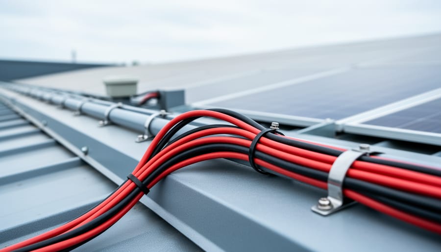
Wire gauge selection significantly impacts voltage drop—thicker wires reduce resistance over long runs from roof to battery.
Undersized Wire (The #1 Problem)
Here’s the thing most RV solar installers don’t want to admit: undersized wiring is the number one culprit behind voltage drop problems. I learned this the hard way during my first major RV solar installation.
Picture this: I’d just finished installing a beautiful 400-watt solar array on my friend’s Class A motorhome. Everything looked professional, the panels were perfectly aligned, and we were both excited to see those batteries charge up. But when we tested the system, we were only getting about 70% of the expected power. I was baffled until I realized my rookie mistake – I’d used 10 AWG wire for a 30-foot run carrying 20 amps. That’s like trying to push a gallon of water through a coffee stirrer.
Here’s what you need to understand: wire gauge directly determines resistance, and resistance creates voltage drop. The smaller the wire gauge number, the thicker the wire and the less resistance it has. Think of it like plumbing – a bigger pipe moves more water with less effort.
Here’s a quick reference chart for copper wire in 12V systems:
For 10-foot runs: 10 AWG handles up to 30 amps, 12 AWG up to 20 amps, 14 AWG up to 15 amps
For 20-foot runs: 8 AWG handles up to 30 amps, 10 AWG up to 20 amps, 12 AWG up to 15 amps
For 30-foot runs: 6 AWG handles up to 30 amps, 8 AWG up to 20 amps, 10 AWG up to 15 amps
The solution to my friend’s motorhome? We replaced that 10 AWG with proper 8 AWG wire, and suddenly his system performed exactly as designed. Sometimes the simplest fixes make the biggest difference.
Corroded connections create resistance that significantly reduces charging efficiency in RV solar systems.
Corroded or Loose Connections
I learned this lesson the hard way during a particularly humid camping trip in Florida. My RV solar system was barely charging, and after some investigating, I discovered crusty green corrosion covering several battery terminals. In the RV environment, corroded and loose connections are among the most common culprits behind voltage drop, and frankly, they’re often the easiest to fix.
RV electrical connections face a perfect storm of challenges. Constant vibration from road travel, temperature swings from scorching days to cool nights, and moisture from condensation or rain all conspire to create connection problems. Corrosion develops when dissimilar metals meet moisture, creating a resistive barrier that voltage struggles to cross. Even a tiny layer of oxidation can cause significant power loss.
To identify problem connections, start with a visual inspection. Look for white, green, or blue crusty buildup around terminals and connectors. Check for any blackened or discolored areas indicating heat damage. Give each connection a gentle wiggle – if anything moves, it’s too loose.
For cleaning, disconnect power first for safety. Mix baking soda and water into a paste and apply it to corroded areas with an old toothbrush. The fizzing reaction neutralizes acid corrosion. For stubborn buildup, use a wire brush or battery terminal cleaner. Rinse with clean water and dry thoroughly.
When reconnecting, tighten fasteners firmly but don’t overtorque – you want snug, not stripped. Apply a thin coating of dielectric grease or petroleum jelly to terminals before reconnecting. This seals out moisture and prevents future corrosion.
Prevention is straightforward: periodically inspect connections every few months, keep terminals sealed with protective grease, and ensure all junction boxes are properly weatherproofed with appropriate sealing.
Long Wire Runs From Roof to Battery
One of the sneakiest culprits in RV solar voltage drop is simply the distance your electrons have to travel. I learned this the hard way on my first RV setup when I mounted beautiful panels on the roof but ran 25 feet of wire down to my battery compartment. Every foot of wire adds resistance, and resistance eats voltage for breakfast.
Think of it like water flowing through a garden hose. The longer the hose, the more pressure you lose before reaching the sprinkler. In electrical terms, longer wire runs mean more copper for electrons to push through, which translates directly to voltage loss. A 20-foot run might drop 0.5 volts, while a 40-foot run could easily lose 1-2 volts or more, depending on your wire gauge.
The good news? You have several practical solutions. First, consider repositioning components to shorten the distance. Can your charge controller move closer to the panels or battery? Sometimes relocating equipment saves you significant wire length. Second, use junction boxes strategically to consolidate connections and minimize overall wire runs. Finally, upgrading to a thicker wire gauge dramatically reduces resistance. Jumping from 10 AWG to 8 AWG or even 6 AWG might cost more upfront, but it preserves precious voltage over long distances, ensuring your batteries get the power they deserve.
Overloaded or Failing Charge Controller
I’ve seen this scenario play out at campgrounds more times than I can count. Your panels are soaking up sunshine, but your batteries barely budge. Often, the culprit is a charge controller that’s either overwhelmed by your panel array or starting to fail.
First, check if your controller is undersized. Add up the total wattage of your panels and divide by your system voltage. If this amperage exceeds your controller’s rating by more than 80%, you’re pushing it too hard. For example, 400 watts of panels on a 12-volt system produces about 33 amps, which would overwhelm a 30-amp controller.
Watch for these warning signs: the controller feels excessively hot to touch, displays error codes, or shows significantly lower input voltage than what you’re measuring directly at the panels. A failing controller might also cycle on and off randomly or display inconsistent readings.
Here’s a quick test: measure voltage at your panel output, then again at the controller input terminals. If you see more than a 1-2 volt drop here (beyond what cable losses explain), your controller may be failing internally. Also check output voltage under load. A healthy quality charge controller should maintain steady voltage regulation.
When controllers fail, replacement is usually your only option, but at least you’ll know exactly what went wrong.
Multiple Series/Parallel Connection Points
Here’s the thing I learned the hard way on my first RV solar setup: every single connection point in your system is a potential troublemaker. When you’ve got panels wired in series, then connected to parallel branches, then running through multiple junction boxes before reaching your charge controller, you’re creating a maze of resistance opportunities.
Each connection introduces contact points where oxidation, loose terminals, or poor crimps can steal voltage. I remember chasing down a persistent voltage drop issue only to discover I had seven separate connection points between my panels and controller. That’s seven chances for something to go wrong.
The solution? Simplify ruthlessly. Aim to minimize junction boxes and intermediate connections wherever possible. If you’re using MC4 connectors, consider whether you really need that extra junction box or if you can run continuous wire instead. When parallel connections are necessary, use quality combiner boxes that consolidate everything in one weatherproof location rather than scattered connection points across your roof.
Think of your wiring like a garden hose: every connector and adapter reduces flow. The most reliable systems keep it simple, with clean, direct runs and the fewest possible interruption points. Your voltage will thank you.
Quick Fixes You Can Do Right Now
When It’s Time to Upgrade Your Wiring
Sometimes the diagnosis reveals something that quick fixes just can’t solve. If you’re consistently measuring significant voltage drop (more than 3-5% under load) despite cleaning connections and tightening terminals, it’s probably time to upgrade your wiring. I learned this the hard way during my first year RVing when I kept chasing ghost problems, only to realize my original 10-gauge wire simply couldn’t handle the amperage my expanded system was pulling.
The telltale signs are pretty clear: your voltage drop calculations consistently show you need thicker wire, your existing wire feels warm to the touch during operation, or you’ve added panels that exceed what your current gauge was designed for. If your wire run is longer than 15 feet and you’re using anything thinner than 10-gauge for a typical 100-watt system, upgrading should be on your radar.
Here’s what to expect: Upgrading to heavier gauge wire is moderately difficult, rated about a 6 out of 10 for DIYers. You’ll need to route new wire through your RV, which often means crawling around in tight spaces and possibly drilling new access holes. Budget around 100-200 dollars for quality marine-grade wire, connectors, and heat shrink, plus a full afternoon of work. The good news? This is truly a set-it-and-forget-it upgrade. You’ll immediately notice your system performing as it should, and you won’t be troubleshooting voltage issues again anytime soon.
Preventing Voltage Drops in Future Installations
The best way to deal with voltage drop? Prevent it from happening in the first place! When I installed my second RV solar system, I learned this lesson the hard way after having to redo connections that weren’t quite right. Now I always tell folks: spend an extra hour in the planning phase, and you’ll save yourself days of frustration later.
Start with proper wire sizing, which is absolutely critical. Don’t just guess or go with whatever wire you have lying around. You need to calculate the right gauge based on your amperage and wire run length. The longer the distance between components, the thicker your wire needs to be to prevent losses. Here’s where I recommend using the interactive wire sizing calculator available on Spheral Solar. Just plug in your system voltage, expected current, and cable length, and it’ll tell you exactly what gauge you need to keep voltage drop under 3 percent.
When planning component placement, think about minimizing distances. Position your charge controller as close to the batteries as possible, and keep your solar panels relatively near the controller. Every extra foot of wire adds resistance. I’ve seen people mount their charge controller at the front of their RV when the batteries are in the back, creating a 20-foot run that just bleeds voltage unnecessarily.
Connection quality matters tremendously too. When you’re setting up proper RV solar wiring, invest in quality crimp connectors and use a proper crimping tool, not pliers. Apply dielectric grease to every outdoor connection to prevent corrosion. Use ring terminals instead of spade connectors wherever possible since they create more contact surface area.
Label everything during installation so future troubleshooting becomes easier, and always leave a little slack in your wiring for future adjustments.
Regular inspection of your RV solar system helps identify voltage drop issues before they significantly impact battery charging.
Here’s the thing about voltage drop troubleshooting: the first time feels overwhelming, but the third or fourth time? You’ll breeze through it. I promise. Every wire you check, every connection you tighten, you’re building skills that’ll serve you for years of RV adventures.
Most voltage drop issues come down to those same handful of culprits we’ve covered: corroded terminals, undersized wires, or loose connections. Nothing exotic. Nothing that requires an electrician’s license to fix. You’ve absolutely got this.
I’ll never forget tracking down a mysterious voltage drop in my own system three summers ago. Spent two hours checking everything twice, convinced I’d need to rewire the whole setup. Turned out to be a single wire connection behind my charge controller that had worked itself loose from road vibration. Ten seconds with a screwdriver, problem solved. Sometimes the simplest explanation is the right one.
Got questions as you work through your troubleshooting? Drop them in the comments below. This community thrives on helping each other out, and chances are someone else has faced the exact same issue. Share your victories too because nothing motivates fellow DIYers like success stories. Happy troubleshooting, and may your voltage always flow strong.
How useful was this post?
Click on a star to rate it!
Average rating 0 / 5. Vote count: 0
No votes so far! Be the first to rate this post.
We are sorry that this post was not useful for you!
Let us improve this post!
Tell us how we can improve this post?
charlesnoble
Here at Spheral Solar, I’m a hands-on solar power enthusiast, constantly exploring and experimenting with DIY solutions. I’m dedicated to sharing my discoveries, insights, and even the bumps I hit along the way, all in the pursuit of a more sustainable future.
Your Multimeter Can Tell You Everything About Your… by Charlesnoble March 8, 2026 Grab your multimeter and set it to AC voltage mode—typically marked as “V~” or “VAC”—which allows you to measure the alternating current output from your solar inverter, the device that converts your panels’ DC power into usable household electricity. You’ll want to verify that your system is delivering the standard…
Why Your DIY Solar Project Needs a Calibrated… by Charlesnoble February 3, 2026 Point your infrared thermometer at your solar panel surface on a sunny afternoon, and you might get a reading of 145°F—but is that number actually accurate? Without proper calibration, that measurement could be off by 10, 20, or even 30 degrees, leading you to misdiagnose hot spots, overestimate efficiency losses,…
Why Your Solar Meter Numbers Don’t Match Your… by Charlesnoble January 20, 2026 Look at your solar meter display right now and locate the kWh reading—this number tells you exactly how much electricity your panels have generated since installation, and if it’s climbing daily, your system is working. Check whether your meter’s digital arrows or symbols are moving forward (you’re using solar power…
Read Your Solar System Like a Pro: What Every Wire… by Charlesnoble October 31, 2025 Locate the single-line diagram in your solar system documentation—it’s your roadmap to understanding how energy flows from panels through inverters to your home’s electrical panel. This schematic shows every critical component: charge controllers, battery banks, breaker boxes, and safety disconnects, all connected by lines representing wire runs with their corresponding…
Why Your RV Appliances Keep Tripping the Breaker… by Charlesnoble November 17, 2025 Turn off shore power and disconnect your battery bank before touching any wire in your RV—this single step prevents the most common DIY electrical accidents. Check your circuit breaker panel ratings against your actual appliance loads, because that microwave drawing 1500 watts on a 15-amp circuit is exactly why you’re…
Why Your Motorhome Electrical System Keeps Failing… by Charlesnoble November 18, 2025 Picture this: You’re three days into a dream cross-country trip when your lights flicker, the refrigerator stops cooling, and you’re left wondering whether to call for expensive roadside assistance or figure it out yourself. I’ve been there, and here’s what I wish someone had told me before my first electrical…
Subscribe for handpicked DIY projects, exclusive tips, and giveaways.
Route your PV wires through UV-resistant conduit within 18 inches of leaving the solar array, securing it every 3 feet with proper clamps to prevent wind damage and code violations. This single step prevents 80% of the wire degradation issues I’ve seen in DIY solar installations over the past decade. Group your positive and negative… Read more: Why Your PV Wire Management Could Fail Inspection (And How to Fix It)
Understand that 6000 volts sounds terrifying but delivers surprisingly low amperage—typically around 120 milliamps for just 3/10,000th of a second per pulse. This combination creates an unforgettable shock that trains animals to avoid the fence without causing lasting harm. The voltage pushes current through thick fur and hide, while the minimal amperage and microsecond duration… Read more: Why 6000 Volts Won’t Kill Your Livestock (But Will Stop Predators Cold)
Check the maximum voltage and current ratings first—these determine whether your controller can actually handle your solar panel array without frying itself on the first sunny day. I learned this the hard way when my first DIY system shut down every afternoon because I’d paired 600 watts of panels with a controller rated for only… Read more: Why Your Solar Setup Needs Both a Charge Controller and Inverter (And How to Pick the Right Ones)


")
")
")

")
")
")
")
")

")
")