Wire Your Solar Panels Wrong and Watch Your Efficiency Disappear
Updated:
Match your wire gauge to your system’s amperage before making a single connection—undersized wire creates dangerous heat buildup and wastes the energy you worked hard to capture. For most residential 12V systems running under 30 amps, 10 AWG copper wire handles the load safely, but calculate your specific needs using voltage drop formulas to prevent losing power over long cable runs between your panels and charge controller.
Choose between series and parallel wiring configurations based on your voltage requirements and shading conditions. Series wiring adds voltage while keeping amperage constant, making it ideal for string inverters and minimizing current-related losses, but one shaded panel drags down your entire string’s performance. Parallel wiring maintains voltage while adding amperage, offering better shade tolerance and redundancy, though it requires larger conductors and more careful overcurrent protection.
Install proper overcurrent protection devices—fuses or circuit breakers—between every major component to prevent electrical fires and equipment damage. Your solar panels need protection on both positive and negative lines, with appropriately rated disconnects at the array, charge controller, battery bank, and inverter locations to meet electrical code and allow safe maintenance.
Ground your entire system correctly using bare copper conductors sized according to your largest circuit wire. This isn’t optional safety theater—proper grounding protects your investment from lightning strikes and prevents dangerous voltage potentials that could energize metal frames and racking.
I learned this lesson after watching a neighbor’s improperly grounded system sustain thousands in damage during a summer storm, while my correctly wired setup weathered the same lightning without a single issue. Getting the fundamentals right from the start saves money, prevents fires, and ensures your solar investment delivers clean power for decades.
Why Wiring Is the Make-or-Break Factor in Solar Efficiency
I learned this lesson the hard way during my first solar installation. I’d spent weeks researching panels and inverters, carefully calculating my energy needs, and positioning everything perfectly on my roof. But I made one critical mistake: I cheaped out on the wiring. Within months, I noticed my system wasn’t producing anywhere near the power it should have been. The culprit? Undersized cables creating resistance and literally turning my solar investment into a heat generator.
Think of your solar wiring like the pipes in your home’s plumbing system. When water flows through a narrow pipe, it encounters friction and pressure loss. The same thing happens with electricity moving through wires that are too thin or poorly connected. This resistance doesn’t just slow things down—it converts precious electrical energy into wasted heat. In a solar system producing hundreds or thousands of watts, even a small percentage of loss adds up to significant money left on the table.
Here’s what most beginners don’t realize: the electricity your panels generate has to travel through potentially dozens of feet of wire before reaching your batteries or inverter. Every connection point, every foot of cable, and every wire gauge decision either helps or hinders that journey. Poor wiring choices can easily cost you 10-15 percent of your system’s output—sometimes more.
The resistance issue becomes even more critical with direct current systems, which most DIY solar setups use. DC power is less forgiving of voltage drops than AC power. When voltage drops due to inadequate wiring, your inverter has to work harder, your batteries charge slower, and your entire system operates below its potential.
The good news? Understanding these principles now means you can make smart wiring decisions from the start. Proper wire sizing, quality connections, and strategic layout planning ensure every photon your panels capture actually contributes to powering your life. That’s why we’re diving deep into this topic—because getting the wiring right is just as important as choosing quality panels themselves.
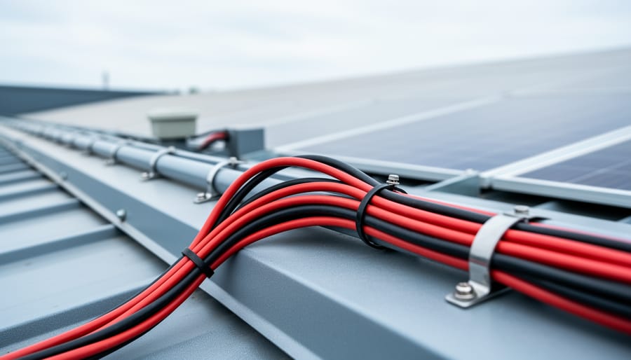
Proper wire connections at solar panel junction boxes are critical for maintaining system efficiency and preventing power loss.
Understanding Your Solar Panel’s Electrical Output
Reading Your Panel’s Specifications Label
Before you start connecting wires, you need to become best friends with that label on the back of your solar panel. I remember staring at mine the first time, completely baffled by all those abbreviations. But once you crack the code, it’s actually pretty straightforward.
Every solar panel has a specifications label listing its electrical characteristics. Think of it as your panel’s ID card. Here’s what those mysterious terms actually mean:
Voc (Open Circuit Voltage) is the maximum voltage your panel produces when nothing’s connected to it—basically when it’s just sitting in the sun doing nothing. For example, a typical residential panel might show 38V. This number matters because you’ll need it to ensure your system doesn’t overload your charge controller or inverter.
Isc (Short Circuit Current) is the maximum current flowing when the panel’s positive and negative terminals are directly connected. You’ll often see something like 9.5A. This helps you size your wiring and protection devices correctly.
Now here’s where it gets practical. Vmp (Voltage at Maximum Power) and Imp (Current at Maximum Power) tell you what your panel actually delivers during normal operation. A panel might have a Vmp of 32V and Imp of 8.5A. Multiply these together and you get your wattage—in this case, about 272 watts.
When planning your system, use our voltage calculator to figure out how these numbers work together in series and parallel configurations. Understanding these four values transforms you from guessing to making informed wiring decisions.
How Weather and Temperature Affect Your Output
Here’s something I learned the hard way during my first solar installation: your panels won’t always produce their rated output. A 300-watt panel rarely delivers a full 300 watts in real-world conditions, and understanding this matters enormously for your wiring choices.
Temperature plays a bigger role than most people realize. Solar panels actually lose efficiency as they heat up. On a scorching summer day when you’d expect maximum power, panels can produce 10-20% less than their rating. Cold, sunny winter days often deliver better performance. This temperature variation affects voltage particularly, which is why calculating wire gauge based solely on nameplate specs can lead to undersized wiring.
Weather conditions matter too. Cloudy days, shade from passing clouds, morning dew, and dust accumulation all reduce output. While your panels might be rated for 8 amps, they’ll frequently operate at 6 or 7 amps under real conditions.
Why does this matter for wiring? You need to size components for peak production moments, not average conditions. When that perfect cool, clear morning hits and your panels surge to full capacity, your wiring must handle it safely without overheating. Always design for maximum possible output, even if you won’t see it constantly.
Series vs. Parallel Wiring: Which Setup Kills Your Efficiency
Series Wiring: When High Voltage Works For You
When you connect solar panels in series, you’re essentially creating a chain where the voltage adds up while the current stays the same. Think of it like stacking batteries end-to-end—each panel’s voltage contributes to the total. If you have three 40-volt panels in series, you’ll get 120 volts flowing through your system.
Here’s where series wiring really shines: long wire runs. I learned this the hard way during my first off-grid cabin project when I placed my charge controller way too far from the panels. Higher voltage means you can use thinner wire without losing efficiency to resistance. That translates to real money saved on copper and easier installation.
Series connections also work beautifully with MPPT (Maximum Power Point Tracking) controllers. These smart devices love higher voltages because they can convert that extra voltage into additional current, squeezing every bit of power from your panels. It’s like having a really efficient transmission in your car.
But here’s the catch—and it’s a big one. Series wiring creates a critical vulnerability to shading. When panels are wired in series, they’re only as strong as their weakest link. If one panel gets shaded, it drags down the entire string’s performance. I once watched a neighbor’s output drop by 80 percent because of shade from a single tree branch across one panel.
For most residential setups, you’ll want to keep your series strings between 2-4 panels, balancing the voltage benefits against shading risks. Always use our voltage calculator to ensure your string voltage stays within your charge controller’s limits—going over can damage expensive equipment.
Parallel Wiring: The Safer Choice for Partial Shade
When I first installed panels on my workshop roof, I learned the hard way about shading issues. A nearby tree would cast shadows across one panel during late afternoon, and my series-wired system would practically shut down. That’s when I discovered the beauty of parallel wiring.
In a parallel configuration, each solar panel connects directly to your charge controller or inverter with its own positive and negative leads. Think of it like multiple rivers flowing into the same lake—each panel operates independently. If one panel gets shaded by a passing cloud, fallen leaves, or that troublesome tree branch, the other panels keep producing at full capacity.
This independence is the main advantage of parallel wiring. Your system becomes remarkably resilient to partial shading, which is common in residential settings where chimneys, trees, or neighboring buildings create shade patterns throughout the day. I’ve seen parallel systems maintain 70-80% output even when one panel is completely shaded, whereas a series system might drop to 20% or less.
The trade-off? Higher current flowing through your wires. While series connections increase voltage, parallel connections stack up the amperage. This means you’ll need thicker gauge wires to safely handle the increased current without overheating or losing efficiency to resistance. For example, three 8-amp panels wired in parallel produce 24 amps combined, requiring substantially beefier wiring than their series counterpart.
You’ll also need a charge controller rated for higher amperage input, which typically costs a bit more upfront.
Series-Parallel Hybrid: Getting the Best of Both
When your solar array grows beyond just a few panels, you’ll often hit the sweet spot where combining both series and parallel connections makes perfect sense. This is where things get interesting—and honestly, more efficient.
Here’s a real-world scenario: Let’s say you’re installing twelve 300-watt panels and your charge controller handles up to 150 volts. Wiring all twelve in series would push you over that limit, while going fully parallel would create massive current that requires expensive, thick cables. The solution? Create three strings of four panels each (series), then connect those strings together (parallel). You’ve just built a series-parallel hybrid system.
I remember Charles telling me about his garage installation where this approach saved him nearly $200 in wiring costs alone. By grouping panels strategically, he kept voltages manageable while avoiding the need for industrial-gauge cables.
The beauty of hybrid wiring is flexibility. You can match your inverter’s voltage window while keeping current at reasonable levels. It also provides some shading resilience—if one string underperforms, the others keep producing.
Use our series and parallel calculator to experiment with different configurations. Input your panel specs and system requirements, and it’ll show you the optimal series-parallel combination for your setup. For arrays with six or more panels, this approach almost always delivers better performance and cost-effectiveness than sticking with simple configurations.
Series wiring configuration connects multiple solar panels to increase voltage output for efficient power transmission to the charge controller.
Choosing Wire Gauge: The Mistake That’s Costing You Power
The Voltage Drop Rule You Can’t Ignore
Here’s something I learned the hard way on my second solar installation: electricity doesn’t flow perfectly through wires. It’s kind of like water pressure dropping as it travels through a long garden hose. This phenomenon is called voltage drop, and in the solar world, there’s a golden rule you need to follow: keep voltage drop under 3%.
Why 3%? Because anything higher means you’re literally losing power between your panels and your battery or inverter. Think of it as money evaporating before it reaches your wallet. On a 12-volt system, a 3% drop means you’re losing about 0.36 volts. That might not sound like much, but multiply that across hours of daily operation, and you’re wasting significant energy.
The main factors affecting voltage drop are wire length, wire thickness (gauge), and the current flowing through it. Longer runs need thicker wires. Higher amperage needs thicker wires. It’s that simple.
Here’s a practical example: if you’re running 30 feet of wire from your panels to your charge controller and your system produces 10 amps, you’ll need at least 10 AWG wire to stay under that 3% threshold. Use our watts to amps calculator to figure out your system’s current first.
To make this easier, Spheral Solar offers a wire gauge calculator tool that does the math for you. Just plug in your distance, voltage, and amperage, and it’ll tell you exactly what wire gauge you need.
Wire Types That Work (and the Ones That Don’t)
Not all wire is created equal, and choosing the right type for your solar installation can mean the difference between a system that hums along for decades and one that becomes a headache. Let me share what I’ve learned through both research and a few expensive mistakes.
For solar applications, you absolutely need wire rated for outdoor use. Look for labels like “sunlight resistant” or “UV resistant” on the insulation. Standard indoor wire will crack and degrade under constant sun exposure, creating serious safety hazards. The most common choice is USE-2 or PV wire, specifically designed for photovoltaic systems. These wires can handle temperature swings, moisture, and years of UV bombardment without breaking down.
When it comes to copper versus aluminum, copper wins for most DIY installations. Yes, aluminum is cheaper and lighter, but copper conducts electricity more efficiently and requires less maintenance. Aluminum connections can oxidize over time, increasing resistance and potentially creating hot spots. Unless you’re running extremely long distances where weight becomes a factor, stick with copper.
The stranded versus solid debate is simpler: use stranded wire for solar panels. Stranded wire is more flexible, making it easier to route through conduit and around obstacles. It also handles vibration better, which matters on rooftop installations where panels can shift slightly. Solid wire is fine for certain stationary connections, but stranded is your go-to for most solar wiring applications. The slight price difference is worth the installation ease and long-term reliability.
Essential Connectors and Junction Boxes
Wire gauge selection directly impacts voltage drop and system efficiency, with thicker wires required for longer distances and higher current applications.
MC4 Connectors: Why Quality Matters More Than You Think
I learned this lesson the hard way during my first solar installation. I bought cheap MC4 connectors online to save a few bucks, and within six months, I was troubleshooting mysterious power drops. When I finally checked the connections, the plastic housings had cracked and moisture had gotten inside, causing corrosion.
Quality MC4 connectors might cost a bit more, but they’re engineered to withstand decades of UV exposure, temperature swings, and weather. Cheap knockoffs use inferior plastic that becomes brittle and metal contacts that corrode easily. The result? Resistance buildup that reduces your system’s output and creates potential fire hazards.
Proper installation is straightforward but critical. Strip your wire to the exact length specified (usually about 8mm), insert it fully into the connector, and crimp it firmly with the proper tool. Hand-crimping or using pliers rarely works well. Once assembled, give each connector a firm tug test—it shouldn’t pull apart with reasonable force.
To verify good connections, use a multimeter to check for continuity and measure voltage drop across each connector pair. You should see virtually no voltage loss. If you’re measuring anything above 0.5 volts under load, investigate immediately. That resistance is costing you power and generating heat.
Junction Box Placement and Weatherproofing
Your junction box is where all your solar panel connections come together, and it needs serious protection from Mother Nature. I learned this the hard way during my second installation when I cheaped out on a standard electrical box instead of using a proper weatherproof enclosure. Three months later, moisture had worked its way inside, causing corrosion that nearly doubled my system’s resistance.
Here’s what works: Always use NEMA-rated junction boxes (NEMA 3R minimum for outdoor use, NEMA 4X for coastal areas with salt air). Mount them where water naturally drains away, never on surfaces where water pools. Charles always positions his boxes with the conduit entries pointing downward to create “drip loops” that prevent water from traveling along the wires into the box itself.
For wire entry points, use liquid-tight flexible conduit with proper compression fittings. Standard conduit connectors will leak eventually. Apply dielectric grease to all connections inside the box to prevent corrosion, and double-check that rubber gaskets are properly seated before closing the lid.
One practical tip from Charles’s Colorado installations: In areas with extreme temperature swings, leave a small service loop of wire inside the box. This prevents connections from stressing as materials expand and contract with temperature changes.
Safety Components That Save Your System (and Your Life)
Fusing Every String: Your First Line of Defense
Every string of solar panels needs its own fuse, installed as close to the panel connections as possible. Think of fuses as tiny guardians that sacrifice themselves to protect your entire system from overcurrent damage. I learned this the hard way when a friend skipped fusing and ended up with melted wiring after a partial shading issue caused unexpected current backflow.
The placement matters tremendously. Install fuses on the positive wire of each string before they combine at your combiner box. This protects against back-feeding current from other strings and prevents fires during fault conditions.
Calculating the proper fuse rating is straightforward but critical. Take your panel’s short-circuit current rating, multiply by 1.56 according to electrical code requirements, and round up to the nearest standard fuse size. For example, if your panels produce 9 amps short-circuit current, you’d need a 15-amp fuse. Our fuse size calculator makes this process quick and foolproof.
Remember, oversized fuses won’t protect effectively, while undersized ones will blow unnecessarily. Getting this right means your system runs efficiently without nuisance trips, and you sleep soundly knowing your investment is protected from electrical hazards that could otherwise cause serious damage.
Disconnect Switches and Breakers: Code and Common Sense
Disconnect switches and breakers aren’t just code requirements—they’re your safety net. I learned this the hard way when a friend tried troubleshooting his system without proper disconnects. Let’s just say the sparks were memorable.
The National Electrical Code requires at least two disconnect points: one between your solar panels and charge controller, and another between your battery bank and inverter. Think of these as emergency stop buttons that let you safely work on any part of your system without risk of electrocution or equipment damage.
Your main solar disconnect should be within sight of your array or clearly labeled if located elsewhere. Use DC-rated disconnect switches specifically designed for solar applications—standard AC switches can arc dangerously with DC current. Mount them in weatherproof enclosures if they’re outdoors.
For breakers, size them at 125% of your maximum circuit current to prevent nuisance tripping. Place your AC breaker as close to your main panel as possible, following local requirements.
Here’s my practical tip: install disconnects in accessible locations where you can reach them quickly during emergencies, but not where curious kids or visitors might tamper with them. Label everything clearly with weatherproof tags indicating voltage levels and what each disconnect controls. Future you will appreciate the clarity when troubleshooting at midnight.
Properly installed weatherproof junction boxes protect critical electrical connections from moisture and environmental damage while organizing multiple wire runs.
Wiring Your Charge Controller and Battery Bank
This is where the magic happens—connecting your solar panels to your battery bank through the charge controller. I’ll be honest, the first time I wired mine, I triple-checked every connection because getting this wrong can damage your batteries or worse. But don’t worry, with careful attention to detail, you’ll nail this.
Your charge controller acts as the brain of your system, managing the power flowing from your panels to your batteries. Start by positioning it as close to your battery bank as possible—ideally within a few feet. This minimizes voltage drop on the high-current battery side, which is crucial because batteries can pull serious amperage during charging.
Let’s talk wire sizing for battery connections. This is different from your panel-to-controller wiring because the current here can be much higher. If you haven’t already, use a battery capacity calculator to determine your system’s charging current needs. For most off-grid setups, you’ll need at least 4 AWG wire for runs under five feet, but check your controller’s specifications. Undersized wires here create heat and waste precious energy.
Polarity is absolutely critical—positive to positive, negative to negative. I always use red wire for positive and black for negative, and I mark each end with tape labels. Connect your battery bank to the charge controller first, before connecting the solar panels. This allows the controller to detect your system voltage and configure itself properly.
Now for grounding, which protects both you and your equipment. Connect a dedicated ground wire from your charge controller’s grounding terminal to your system ground. Many people overlook this step, but it’s essential for safety and can prevent phantom voltage issues that drive you crazy during troubleshooting.
Use properly rated fuses or breakers on both the battery and solar sides—typically within 18 inches of each component. This protects against short circuits and makes maintenance safer down the road.
Testing and Troubleshooting Your Wiring Installation
The Pre-Power Checklist
Before you power up your system, let’s walk through a simple testing routine that’ll save you from potential headaches down the road. I learned this lesson the hard way when I once skipped this step and spent three hours troubleshooting what turned out to be one loose wire connection.
Start with your multimeter set to DC voltage. With everything still disconnected from your charge controller or inverter, test each solar panel individually. You should see voltage readings that match your panel’s specifications, give or take a few volts depending on sunlight conditions.
Next, verify your series connections. Touch the multimeter probes to the ends of your string—you should see the sum of all panel voltages. For example, four 20-volt panels in series should read around 80 volts. If the numbers don’t add up, you’ve got a connection issue to address.
Now check your parallel connections by measuring voltage across each string. All strings should show similar readings. Significant differences might indicate a problem with individual panels or wiring.
Finally, use your multimeter’s continuity setting to verify your ground connections. You should hear a beep confirming solid connections throughout your grounding system. Don’t rush this step—proper grounding protects both you and your investment.
When Your System Underperforms: Wiring Issues to Check First
When your solar system isn’t producing the power you expected, wiring issues are often the culprit. I learned this the hard way when Charles helped me diagnose a system that was underperforming by nearly 30 percent—turns out, a few simple checks would have saved me weeks of head-scratching.
Start by inspecting all visible connections for corrosion, which appears as white, green, or blue crusty buildup around terminals. Even minor corrosion creates resistance that steals your precious watts. Next, check for loose connections by gently tugging on wires at junction boxes and combiner boxes—they shouldn’t budge.
Use a multimeter to measure voltage drops along your wire runs. A significant drop between your panels and charge controller indicates undersized wiring or a bad connection somewhere in the line. Compare your readings to what your panels should produce under current conditions.
Look for physical damage too: UV-degraded insulation, pinched wires, or cables rubbing against sharp edges. These issues might not cause immediate failure but create ongoing efficiency losses.
Finally, verify that all connections are tight and properly rated. Inadequate crimps or connectors not designed for DC applications can create hot spots that waste energy and pose safety risks.
Real-World Wiring Examples from the Field
Over the years, I’ve helped friends and family tackle various solar projects, and I’ve learned that real installations rarely go exactly as planned. Let me share three experiences that taught me valuable lessons about wiring decisions.
My buddy Jake converted his Sprinter van into a weekend adventure vehicle and wanted a simple solar setup. We installed two 100-watt panels on the roof connected in parallel. Here’s why: vans experience a lot of partial shading when parked near trees or buildings, and parallel wiring meant one shaded panel wouldn’t drag down the other’s output. We used 10 AWG wire for the short 8-foot run to the charge controller mounted inside a cabinet. The big lesson? Leave extra wire length at both ends. When Jake later repositioned his battery bank for better weight distribution, we were grateful for that slack. We also learned to use marine-grade wire with tinned copper strands because regular wire corrodes quickly in the humid van environment.
The shed project was for my neighbor Sandra, who wanted to power her pottery studio about 50 feet from her house. She had four 250-watt panels, and we chose series wiring to create higher voltage, which reduced power loss over that longer distance. We stepped up to 8 AWG wire to handle the current safely. The unexpected challenge? Rodents. Within six months, mice had chewed through the conduit near the shed’s foundation. Now I always recommend metal conduit for the first three feet above ground level, especially in outbuildings. It costs a bit more upfront but saves headaches later.
The most ambitious project was my cousin’s off-grid cabin. With eight panels producing 2,400 watts total, we used a series-parallel configuration: two strings of four panels each. This balanced voltage and current while providing redundancy. The lesson learned here involved disconnect switches. Building code required them, but they also proved invaluable during a lightning storm when we could quickly isolate the array. We installed disconnects at the array, before the charge controller, and at the battery bank. It seemed like overkill during installation, but those switches gave everyone peace of mind.
Each project reinforced that good wiring isn’t just about following formulas. It’s about anticipating real-world conditions and planning for future adjustments.
You’ve made it through the essentials of solar panel wiring, and here’s what I want you to remember: this is absolutely something you can do. When I started my first solar project years ago, the wiring intimidated me more than anything else. But once I realized it’s really just following patterns, respecting safety protocols, and double-checking connections, everything clicked into place.
The beauty of solar wiring is that it’s methodical. There’s no mystery to it. You measure your voltage, calculate your wire gauge, ensure proper polarity, and connect everything systematically. Yes, you need to pay attention to detail, but that’s true whether you’re wiring solar panels or building a bookshelf. The difference here is that getting it right means years of reliable, clean energy powering your home.
Before you grab your tools, take advantage of Spheral Solar’s interactive calculators to verify your system sizing and wiring requirements. These tools take the guesswork out of the math and help you avoid costly mistakes before you make your first purchase.
Now it’s your turn. The DIY solar community thrives when we share what we’ve learned. Whether you’re planning your first panel installation or you’ve already got a system humming along, your experience matters. Join our community forums, share photos of your setup, ask questions when you’re stuck, and celebrate your successes with people who understand the satisfaction of generating your own power. We’re all learning together, and your project might be exactly what inspires someone else to take that first step.
How useful was this post?
Click on a star to rate it!
Average rating 0 / 5. Vote count: 0
No votes so far! Be the first to rate this post.
We are sorry that this post was not useful for you!
Let us improve this post!
Tell us how we can improve this post?
charlesnoble
Here at Spheral Solar, I’m a hands-on solar power enthusiast, constantly exploring and experimenting with DIY solutions. I’m dedicated to sharing my discoveries, insights, and even the bumps I hit along the way, all in the pursuit of a more sustainable future.
Stop Burning Out Your Solar Gear: Why Electrical… by Charlesnoble February 22, 2026 Grab your multimeter and calculator—understanding electrical conversions transforms confusing numbers into actionable data for your solar setup. When I first started working with solar panels, I’d stare at spec sheets showing watts, amps, and volts, completely baffled about which numbers actually mattered for sizing my components. That confusion nearly led…
Stop Guessing Your Battery Power: The Conversion… by Charlesnoble October 28, 2025 Grab your battery specifications and check three numbers that matter: amp-hours (Ah) tells you total capacity like a fuel tank size, watt-hours (Wh) reveals actual energy storage accounting for voltage differences, and reserve capacity (RC) shows real-world runtime at a steady draw. These measurements aren’t interchangeable labels for the same…
Solar Panel Series and Parallel Calculator by Charlesnoble July 3, 2023 Solar panel series and parallel calculator the wattage of a solar array in series, parallel, and series-parallel configs. This way, you can readily tell the optimal configuration for your solar power system. Some solar panels in series will generate more power than when they have parallel wiring. Contrarily, others have…
How Much Power Does an 8kW Solar System Actually… by Charlesnoble March 24, 2026 An 8kW solar system typically generates between 24 and 40 kWh per day, depending on your location, season, and installation quality. That’s enough to power most average homes completely, but the reality is more nuanced than a single number can capture. I remember installing my first 8kW array in Arizona…
How Many kWh Does Your Solar System Actually Need?… by Charlesnoble November 29, 2025 Calculate your daily energy consumption by checking your utility bill for the monthly kilowatt-hour (kWh) usage, then divide by 30 to get your average daily number. This single figure becomes your North Star for sizing any solar system, whether you’re powering a full household, weekend cabin, or portable camping setup.…
Calculate Your Solar Panel kWh Output Before You Buy… by Charlesnoble January 29, 2026 Grab your solar panel specs and electricity bill—you’re about to discover exactly how many kilowatt-hours your solar setup can generate and whether it’ll actually cover your energy needs. Most people dive into solar projects with enthusiasm but fuzzy math, leading to oversized systems that waste money or undersized ones that…
Subscribe for handpicked DIY projects, exclusive tips, and giveaways.
Route your PV wires through UV-resistant conduit within 18 inches of leaving the solar array, securing it every 3 feet with proper clamps to prevent wind damage and code violations. This single step prevents 80% of the wire degradation issues I’ve seen in DIY solar installations over the past decade. Group your positive and negative… Read more: Why Your PV Wire Management Could Fail Inspection (And How to Fix It)
Understand that 6000 volts sounds terrifying but delivers surprisingly low amperage—typically around 120 milliamps for just 3/10,000th of a second per pulse. This combination creates an unforgettable shock that trains animals to avoid the fence without causing lasting harm. The voltage pushes current through thick fur and hide, while the minimal amperage and microsecond duration… Read more: Why 6000 Volts Won’t Kill Your Livestock (But Will Stop Predators Cold)
Check the maximum voltage and current ratings first—these determine whether your controller can actually handle your solar panel array without frying itself on the first sunny day. I learned this the hard way when my first DIY system shut down every afternoon because I’d paired 600 watts of panels with a controller rated for only… Read more: Why Your Solar Setup Needs Both a Charge Controller and Inverter (And How to Pick the Right Ones)


")
")


")
")