Why 2-Wire RS485 Is the Smartest Choice for Your DIY Solar Monitoring System
Updated:
Check your solar inverter’s communication ports right now – if you see two screw terminals labeled A and B (or D+ and D-), you’re looking at 2-wire RS485, the most common communication protocol in DIY solar monitoring setups. This simple two-wire system lets your solar equipment talk to monitoring devices, allowing you to track power production, battery status, and system health from your phone or computer.
RS485 works by sending data through a twisted pair of wires, where voltage differences between the two wires represent your data. Think of it like a two-lane highway where information travels in both directions, but unlike WiFi or Bluetooth, these wired signals can stretch up to 4,000 feet without losing strength. That’s why manufacturers like Victron, Growatt, and SMA chose RS485 – it’s bulletproof against the electrical noise your inverters and charge controllers generate.
I learned this the hard way three years ago when my first solar monitoring attempt using WiFi adapters kept dropping connections. The moment I switched to a direct RS485 connection with a simple USB adapter, everything just worked. No signal drops, no mysterious disconnections, just reliable data flowing every second.
Understanding 2-wire RS485 means grasping three core concepts: it’s a physical connection method (those two wires), a communication standard (how devices format their messages), and surprisingly forgiving for beginners. You don’t need an engineering degree – just the right cable, proper polarity, and a 120-ohm termination resistor at each end of long runs. The protocol handles multiple devices on one cable, meaning your inverter, battery monitor, and charge controller can all share the same two wires.
What Exactly Is 2-Wire RS485? (And Why Solar Folks Love It)
The Two Wires That Do All the Work
At the heart of RS485’s reliability are just two simple wires, typically labeled A and B. That’s it. No fancy shielding required for most solar installations, no complex cable assemblies, just two conductors doing all the heavy lifting.
Here’s the elegant part: these wires work together by carrying opposite voltages. When wire A is at a higher voltage than wire B, that represents one state (let’s say a “1” in digital terms). When wire B is at a higher voltage than wire A, that’s the opposite state (a “0”). The actual data travels through these voltage differences, not through any single wire’s absolute voltage level.
I remember when Charles first explained this to me during a community workshop. He held up a twisted pair of wires and said, “Think of it like a seesaw. One side goes up, the other goes down. It’s that constant push-pull that makes the message clear, even when conditions aren’t perfect.”
This differential signaling is why RS485 laughs in the face of electrical noise that would scramble other communication methods. Solar installations are electrically noisy environments with inverters switching thousands of times per second and DC current flowing everywhere. But here’s the magic: when electrical interference hits your cable, it typically affects both wires equally. Since RS485 only cares about the difference between A and B, that common noise just cancels itself out.
The system looks at the voltage gap between the wires, not the individual voltages. Noise added equally to both? Ignored. This self-correcting characteristic makes RS485 incredibly forgiving in real-world solar setups where perfect conditions rarely exist.
The simplicity of 2-wire RS485 communication relies on just two conductors to reliably transmit data over long distances in solar installations.
RS485 vs. 4-Wire: What’s the Real Difference?
Here’s something that confused me when I first started diving into RS485 for my solar setup: I kept seeing references to both 2-wire and 4-wire RS485. Are they completely different? Do I need the 4-wire version?
The good news is, it’s simpler than it sounds. Both are RS485, just configured differently. 2-wire RS485 uses half-duplex communication, meaning data travels in both directions but not simultaneously—think of it like a walkie-talkie where you take turns talking. It uses just two wires: typically labeled A and B or D+ and D-.
4-wire RS485, on the other hand, uses full-duplex communication with separate transmit and receive pairs, allowing simultaneous two-way communication. While this sounds fancy, it’s rarely necessary for solar monitoring applications. Your inverter and monitoring devices work perfectly fine taking turns sharing information.
For DIY solar monitoring, 2-wire is what you’ll almost always use. It’s what manufacturers like Growatt, SolarEdge, and most other inverter brands implement in their communication ports. The 4-wire configuration is typically reserved for industrial applications requiring constant, high-speed bidirectional data flow.
When you’re shopping for cables or adapters, stick with 2-wire unless your specific equipment manual explicitly requires otherwise. You’ll save money and avoid unnecessary complexity.
How 2-Wire RS485 Stacks Up Against CAN and Ethernet for Solar Monitoring
When RS485 Beats the Competition
Let me tell you about the situations where 2-wire RS485 really shines. I learned this the hard way when I tried using standard USB cables for my first solar monitoring setup – and quickly discovered my 15-foot limitation.
If you need to run cables over long distances, RS485 is your best friend. While USB typically caps out around 15 feet and Ethernet starts getting unreliable past 300 feet without repeaters, RS485 can reliably transmit data up to 4,000 feet. That’s nearly three-quarters of a mile! This makes it perfect for those solar installations where your inverter sits on one side of the property and your battery bank lives in the garage on the other side.
Harsh outdoor environments are another area where RS485 dominates. The protocol was designed for industrial settings, which means it handles electrical noise, temperature swings, and interference like a champ. I’ve seen RS485 connections running flawlessly in dusty barns, humid coastal areas, and even alongside high-voltage lines that would wreak havoc on more delicate communication systems.
Budget-conscious installations benefit enormously from the two-wire design. You’re using less copper, simpler connectors, and often cheaper cable overall. When you’re already investing thousands in solar panels and batteries, saving money on communication cables adds up quickly.
The real magic happens when you need to connect multiple devices on a single line. RS485 supports up to 32 devices on one cable run – perfect for monitoring several charge controllers, inverters, and battery monitors simultaneously. I’ve helped friends set up systems connecting five different devices using just one twisted pair of wires, something that would require a complicated network switch setup with Ethernet.
For solar applications specifically, this multi-drop capability means you can monitor your entire system’s performance from panels to batteries to inverters without running separate cables everywhere.
Where CAN or Ethernet Might Make More Sense
Look, I’m a huge fan of RS485 for solar monitoring—it’s gotten me through dozens of projects without breaking a sweat. But honesty matters in the DIY community, so let’s talk about when other options might actually serve you better.
If you’re working with a small, single-inverter setup right next to your home network, Ethernet might be the simpler choice. Seriously. When your inverter sits five feet from your router and already has an Ethernet port, why complicate things? Just plug in a cable and you’re done. The setup is more straightforward for folks already comfortable with home networking, and you won’t need to learn about termination resistors or polarity.
CAN bus deserves consideration if you’re building a battery management system or working with electric vehicle components. It’s the standard in automotive applications, so if your battery cells or BMS already speak CAN, fighting that choice doesn’t make much sense. I learned this the hard way on a camper van project where I tried forcing RS485 into a system that really wanted CAN.
High-speed data logging presents another scenario. If you need to capture inverter data multiple times per second for detailed power quality analysis, modern Ethernet-based protocols handle that bandwidth better than RS485. Think utility-scale installations or research projects rather than typical home monitoring.
The real question isn’t which protocol is universally best—it’s which fits your specific situation. For most DIY solar monitoring with multiple devices spread across distances, RS485 still wins. But don’t let anyone, including me, push you toward complexity you don’t actually need.
The Real-World Benefits of 2-Wire RS485 in Your Solar Setup
It’s Ridiculously Simple to Wire (Even If You’re New to This)
Here’s the beauty of 2-wire RS485: you literally only need two wires. That’s it. No color-coding confusion, no trying to remember which of eight wires does what while you’re balanced on a ladder in the sun.
I remember my first solar monitoring installation. I’d spent weeks researching communication protocols, terrified I’d mess something up. When I discovered RS485 only needed two wires, I actually laughed. After dealing with complicated home networking projects, this felt almost too easy.
The forgiving nature really shines when you’re running cables across your roof or out to remote arrays. Made a connection that’s a bit loose? RS485’s differential signaling handles minor imperfections gracefully. Accidentally reversed the wires? Just swap them back – no harm done in most cases. This matters tremendously when you’re troubleshooting from ground level and your inverter is mounted twenty feet up.
For beginners, this simplicity means less time second-guessing yourself and more time actually getting your monitoring system running. You’re connecting A to A and B to B on each device. If you can use a screwdriver and follow a simple diagram, you can wire RS485. The protocol was designed for industrial environments where reliability trumps complexity, and that robustness works perfectly for DIY solar installations.
Distance Is Your Friend: Running Cables Up to 4,000 Feet
One of the standout features of 2-wire RS485 is its incredible range. We’re talking about reliable communication over distances up to 4,000 feet, which is roughly three-quarters of a mile. For context, that’s longer than 13 football fields laid end to end.
This distance capability is a game-changer for off-grid setups. I remember helping my neighbor Charles monitor his solar array that sits a quarter-mile from his barn. With RS485, he runs a simple twisted pair cable from his charge controller to the monitoring display in his workshop without needing signal boosters or repeaters. It just works.
This makes RS485 perfect for properties where your solar equipment isn’t close to where you want to monitor it. Maybe your panels are on a detached garage, your batteries in a shed, or you’ve got RV solar systems parked at the far end of your property. The long-distance capability means you’re not forced to install monitoring equipment right next to your batteries or inverter.
Compare this to USB, which maxes out around 15 feet, and you’ll understand why RS485 remains the standard for distributed solar installations where components spread across your property.
RS485 cables connect multiple solar devices in a daisy-chain configuration, making installation straightforward even for DIY enthusiasts.
Daisy-Chaining Multiple Devices Without the Headache
Here’s one of my favorite things about RS485—you can daisy-chain up to 32 devices on a single pair of wires. No need for separate cables running back to each solar charge controller, inverter, or battery monitor. Just run one continuous line from device to device, and they all talk to each other like neighbors chatting over a fence.
I learned this the hard way on my first system when I tried connecting solar charge controllers with individual cables back to a central hub. What a mess! With RS485, you simply connect A to A and B to B at each device, moving down the line. Think of it like old-fashioned Christmas lights that connect end-to-end.
Now, about that 32-device limit—don’t panic. For most home solar setups, you’ll never hit it. A typical system might have two charge controllers, an inverter, and a battery monitor. That’s only four devices. Even ambitious setups with multiple battery banks and monitoring points rarely exceed ten devices. The 32-device maximum is mainly relevant for large commercial installations or complex off-grid compounds.
When planning your solar combiner box wiring, just remember to keep your daisy-chain sequential and organized.
Built to Handle Solar’s Harsh Reality
Solar installations aren’t exactly gentle environments. Between the electrical noise from inverters switching thousands of times per second and temperature swings from freezing mornings to scorching afternoons, your monitoring system needs to be tough.
That’s where RS485 really shines. The protocol uses differential signaling, meaning it sends data on two wires as opposite signals. When electrical noise hits both wires equally, the receiver simply ignores it by measuring the difference between them. I learned this the hard way when my first solar monitor kept dropping connections until I switched to RS485—suddenly, rock-solid communication even with the inverter running full tilt.
RS485 also handles temperature extremes beautifully, operating reliably from -40°F to 185°F. Your rooftop equipment might bake in summer sun, but RS485 keeps communicating without missing a beat.
Setting Up Your 2-Wire RS485 Network: A Step-by-Step Walkthrough
What You’ll Actually Need (The Shopping List)
Let me share what I’ve learned about gathering the right gear without breaking the bank. Here’s your straightforward shopping list:
First up, you’ll need an RS485-to-USB adapter. These little converters let your computer talk to your solar equipment and typically cost between $15-30. I’ve had good luck with basic CH340-based adapters from online retailers, though if you want bulletproof reliability, the FTDI-based versions run around $40.
For cabling, standard Cat5e or Cat6 ethernet cable works beautifully and you probably have some lying around already. You only need two of the eight wires inside for RS485 communication. A 50-foot spool runs about $15-20 at any hardware store.
Don’t forget termination resistors. You’ll need 120-ohm resistors at both ends of your communication line, usually a pack of five costs under $5 at electronics suppliers or even Amazon.
Grab some quality wire tools if you don’t already have them. Basic wire strippers and a small screwdriver set will handle most connections.
Budget-friendly tip: Many RS485 adapters come with terminal blocks included, saving you a few extra dollars. Total investment? Around $30-50 gets you everything needed to start monitoring your solar setup.
Wiring It Up: The Physical Connection
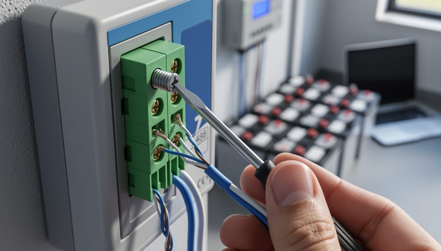
Getting your RS485 wires connected correctly is simpler than you might think, but attention to detail makes all the difference. Let me walk you through this like I’m right there with you at your installation.
First things first: RS485 uses just two wires, typically labeled A and B (sometimes called D+ and D-). Think of them as the positive and negative of your communication highway. The golden rule? Keep your polarity consistent across all devices. Connect A to A and B to B throughout your entire system. I learned this the hard way when I spent two hours troubleshooting a connection, only to discover I’d swapped the wires at one inverter.
For cable routing in solar installations, run your RS485 cable separately from high-voltage AC lines. Keep at least 12 inches of separation to avoid electromagnetic interference that can scramble your data signals. Use twisted pair cable, which naturally resists interference by canceling out electrical noise. Most solar equipment suppliers sell pre-made RS485 cables, but standard Cat5 Ethernet cable works perfectly fine and costs less.
When connecting multiple devices, wire them in a daisy-chain configuration rather than a star pattern. This means going from your monitoring device to inverter one, then from inverter one to inverter two, and so on. Don’t create branches or split the cable.
For outdoor installations, weatherproofing outdoor connections is absolutely essential. Use junction boxes with proper IP ratings and seal cable entries with appropriate grommets. Moisture is your enemy here, causing corrosion and communication failures down the road.
Proper weatherproofing of RS485 connections ensures reliable communication in harsh outdoor solar environments.
Termination Resistors: Don’t Skip This Part
Here’s something I learned the hard way after chasing gremlins in my solar monitoring setup for hours: those little 120-ohm resistors aren’t optional decoration. They’re essential for clean RS485 communication.
Think of your RS485 network like a highway. Without termination resistors at both ends, your data signals bounce back like cars hitting a wall and ricocheting backward, creating chaos. These reflections cause garbled messages, random dropouts, and the kind of frustration that makes you question your life choices.
The fix is beautifully simple. You need exactly two 120-ohm resistors—one at each end of your RS485 cable. Not in the middle. Not on every device. Just the two endpoints. If your charge controller is at one end and your monitoring computer at the other, those are your spots.
Most modern solar equipment has built-in termination you can enable with a DIP switch or jumper. Check your manual first before adding external resistors. If you need to add them yourself, connect each resistor between the A and B terminals at each endpoint.
I keep a handful of these resistors in my toolkit because at about twenty cents each, they’re the cheapest insurance policy for reliable communication you’ll ever buy.
Connecting your solar monitoring system to a computer requires only a simple RS485-to-USB adapter and basic cable connections.
Getting Your Computer to Talk to the System
Getting your computer to chat with your solar system is easier than you might think! You’ll need an RS485-to-USB adapter (available online for around $15-30), which acts as a translator between your computer and the 2-wire system. Simply plug the adapter into your computer’s USB port and connect the A and B wires from your solar equipment to the corresponding terminals on the adapter.
For software, you’ve got options. Solar-Log is popular among DIYers for its user-friendly interface, while tech-savvy folks might explore custom solutions using Python or similar programming tools. Many inverter manufacturers also offer free monitoring software that works perfectly well.
To verify everything’s working, open your chosen software and look for incoming data packets. If you see readings from your inverter or charge controller, congratulations—you’re connected! If not, double-check your wiring polarity and termination resistors. When I first set mine up, I had the A and B wires reversed. One quick swap, and data started flowing beautifully.
Common Problems and How to Fix Them (Before You Pull Your Hair Out)
No Communication? Check These Three Things First
When your RS485 network goes silent, don’t panic! I’ve been there more times than I’d like to admit, and usually the fix is simpler than you think. Let’s walk through the three most common culprits in order.
First, double-check your A and B wiring. I know it sounds obvious, but mixed-up polarity is the number one reason systems fail to communicate. Pull out your multimeter and verify each connection point-to-point. Your A terminal on device one should connect to A on device two, and same for B. If you accidentally swapped them, no data will flow. Pro tip: use different colored wires (like red for A and black for B) to avoid this headache in the first place.
Second, inspect your termination resistors. You should have a 120-ohm resistor at each end of your RS485 line – that’s it, just two total. Too many resistors or missing ones both cause communication headaches. If you’re unsure, disconnect everything and measure resistance between A and B. You should see approximately 60 ohms if both terminators are properly installed.
Finally, verify power to every device. It’s embarrassingly easy to miss a dead power supply or blown fuse. Check each device individually shows its power indicator light or display active before troubleshooting further.
Intermittent Connection Issues
Nothing’s more frustrating than seeing your solar monitoring drop in and out randomly. I learned this the hard way when my system would show perfect data one minute, then nothing the next. Here’s what’s usually going on and how to fix it.
Poor cable quality is often the culprit. Those cheap ethernet cables or random wire spools from your garage? They’re not designed for RS485’s signal requirements. The twisted pairs inside need to be properly matched, and bargain cables often aren’t. I switched to proper shielded twisted pair cable rated for RS485, and my connection issues disappeared almost overnight. Look for cable specifically labeled as RS485 or industrial communication cable.
Loose connections are another sneaky problem. Over time, vibration or temperature changes can cause screw terminals to loosen slightly. Every few months, I go through and gently tighten each connection point. Just be careful not to overtighten and damage the terminals. A little snug is all you need.
Electrical noise from your inverters can also wreak havoc on communication signals. These devices generate significant electromagnetic interference. The solution? Keep your RS485 cable at least six inches away from AC power cables, and if they must cross, do so at right angles. Using shielded cable with proper grounding helps tremendously too. When I rerouted my communication cables away from my inverter’s AC output, my intermittent dropouts stopped completely.
When One Device Won’t Join the Party
When just one device refuses to communicate, it’s usually a configuration mismatch rather than a wiring problem. I learned this the hard way when my inverter sat stubbornly silent while everything else chattered away perfectly.
Start by verifying the device address. Each device needs a unique number, and if two share the same address or your monitoring software is looking for the wrong one, communication fails. Check your device’s display or configuration menu against what your system expects.
Next, confirm the baud rate matches across all devices. If your charge controller runs at 9600 baud but your monitoring system expects 19200, they’ll never understand each other. It’s like trying to have a conversation when one person talks twice as fast.
Finally, dig into the manufacturer documentation. Some devices use slight variations of the RS485 protocol or require specific initialization commands. The manual might reveal compatibility quirks or special settings that aren’t obvious. When in doubt, the manufacturer’s tech support has usually heard your exact problem before and can point you toward the solution quickly.
My Personal Experience: What I’ve Learned Wiring RS485 in Solar Systems
I’ll be honest with you – my first RS485 project was a bit of a mess. I had just installed my third solar panel array and was excited to monitor everything from a single interface. I grabbed some Cat5 cable I had lying around, connected my charge controller to my inverter using what I thought was the right wiring, and… nothing. Absolutely nothing.
The problem? I hadn’t twisted the wires properly, and I definitely didn’t understand termination resistors. After three frustrating hours of troubleshooting, I finally discovered that those 120-ohm resistors aren’t optional – they’re essential for preventing signal reflections, especially on longer cable runs. Once I added them at both ends of my 30-foot run, everything sprang to life.
My biggest lesson learned came from a rooftop installation where I initially ran the RS485 cable right alongside my AC power lines. The data was garbled constantly, with random dropouts every few minutes. A fellow DIYer in an online forum suggested separating the cables by at least six inches, and that simple change solved everything. Electromagnetic interference is real, folks.
Here’s something I wish I’d known earlier: labeling matters tremendously. When you’re connecting multiple devices – I now have five on my network – you need to clearly mark A and B terminals. I created a simple chart showing which terminal connects to which wire color, and I keep it laminated near my equipment. Trust me, six months later when you need to add another device, you’ll thank yourself.
The most rewarding moment? Watching real-time data flow from my garage-mounted batteries to my living room display. That first successful connection made all the trial and error worthwhile.
So where does that leave us? After diving into the technical details, comparing options, and walking through real-world implementations, I keep coming back to the same conclusion: 2-wire RS485 is simply the best practical choice for most DIY solar monitoring projects. It’s not the flashiest option out there, and it won’t win any speed contests against Ethernet or WiFi, but that’s not what matters when you’re running cables from your solar array to your charge controller to your battery monitor.
What matters is that it works reliably, costs next to nothing, and doesn’t require you to become a networking expert just to see your battery voltage. I learned this the hard way after overcomplicating my first monitoring setup with expensive wireless modules that dropped connections every time the weather changed. Sometimes the oldest, simplest solution really is the best one.
Yes, there’s a whole ecosystem of monitoring options available. Cloud-based systems, smartphone apps, CAN bus networks, and all sorts of sophisticated solutions exist. They all have their place. But for someone just starting out, or even for experienced DIYers who value reliability over bells and whistles, 2-wire RS485 offers an unbeatable balance of simplicity, reliability, and cost.
My advice? Start simple. Get a basic RS485 adapter, connect one device, and watch the data flow. You can always expand later, adding more devices as your confidence and your system grow. The beauty of RS485 is that it scales with you without requiring a complete redesign.
I’d love to hear about your own RS485 experiences. What worked? What didn’t? Share your stories in the comments below and let’s build this knowledge together.
How useful was this post?
Click on a star to rate it!
Average rating 0 / 5. Vote count: 0
No votes so far! Be the first to rate this post.
We are sorry that this post was not useful for you!
Let us improve this post!
Tell us how we can improve this post?
charlesnoble
Here at Spheral Solar, I’m a hands-on solar power enthusiast, constantly exploring and experimenting with DIY solutions. I’m dedicated to sharing my discoveries, insights, and even the bumps I hit along the way, all in the pursuit of a more sustainable future.
Why Your RV Solar Panels Aren’t Charging (And How to… by Charlesnoble November 30, 2025 Check your multimeter readings at each connection point along your solar charging path—from panels to charge controller to battery—to pinpoint exactly where voltage disappears. Most RV solar systems lose 10-30% of their potential power to voltage drop, but this invisible thief often goes undetected until you systematically measure and compare…
Why Your Solar Array Needs Proper Grounding (Before… by Charlesnoble November 24, 2025 Connect your solar array’s metal frame to a grounding rod driven at least eight feet into the earth near your installation. This creates a safe path for electrical faults and lightning strikes to dissipate harmlessly into the ground instead of through your home’s wiring or, worse, through you. Install grounding…
Why Connecting Your Solar Panel Directly to a… by Charlesnoble March 11, 2026 The short answer is yes, you can physically connect a solar panel directly to a battery, but you absolutely shouldn’t in most cases. Without a charge controller acting as the middleman, you’re essentially playing Russian roulette with your battery’s lifespan and potentially creating a fire hazard. I learned this lesson…
Why Your Solar Panel’s J-Box Matters More Than You Think by Charlesnoble January 8, 2026 Flip over any solar panel and you’ll spot a small weatherproof box attached to the back—that’s the junction box, or j-box, and it’s the critical gateway between your panel’s delicate solar cells and your entire electrical system. Understanding this component isn’t just technical curiosity; it’s essential for anyone wiring their…
Why Your 1500V DC Solar System Needs the Right… by Charlesnoble May 22, 2026 When I first upgraded my solar array to 1500V, I learned quickly that the combiner box isn’t just another component—it’s the critical safety hub protecting your entire system from potentially catastrophic overcurrent events. This unassuming metal enclosure sits between your solar panel strings and inverter, consolidating multiple DC inputs while…
Why Your DIY Solar System Needs a 4 String PV… by Charlesnoble January 27, 2026 Connect your solar panel strings to a single positive and negative output cable using a 4 string PV combiner box—the essential junction point that safely consolidates power from four separate string circuits before feeding your charge controller or inverter. This weatherproof enclosure houses individual fuses or circuit breakers for each…
Subscribe for handpicked DIY projects, exclusive tips, and giveaways.
A portable power station will typically run your camping devices for anywhere from a few hours to several days on a single charge, depending on what you’re powering and the station’s capacity. As for lifespan, most quality units last between 3 to 10 years before the battery degrades enough to need replacement. The distinction matters… Read more: Your Portable Power Station Won’t Last as Long as You Think (Here’s Why)
A J1772 solar charger combines a standard J1772 charging connector (the same Type 1 plug used by most North American EVs and electric bikes) with solar panels and battery components to create an off-grid or grid-supplemented charging system. You’ll need three core elements: solar panels (typically 400-800 watts for practical ebike charging), a battery storage… Read more: How to Choose a J1772 Solar Charger for Your Ebike: A Buying Guide
Installing a whole house ventilation system powered by solar takes about 6 to 8 hours for a moderately skilled DIYer and delivers continuous fresh air circulation without touching your electric bill. The core method involves mounting a solar panel on your roof to power an intake or exhaust fan, routing ductwork through your attic or… Read more: How to Install a Whole House Ventilation System Using Solar Power


")
")
")

")
")
")
")
")

")
")