How to Size Low Voltage Circuit Protection for Your DIY Solar System
Updated:
Low voltage circuit protection in DIY solar systems boils down to matching the right fuse or breaker to your wire size and expected current, not to the capacity of your battery bank or inverter. Most fires and equipment failures happen when people oversize protection devices, thinking bigger is safer, when the opposite is true. Your protection device exists to save the wire from melting before it becomes a fire hazard.
I’ve seen too many solar setups where someone installed a 40-amp fuse on 10 AWG wire because their charge controller could handle 40 amps. The problem? That wire is only rated for 30 amps in typical conditions. When a short circuit happens, that fuse takes too long to blow, the wire heats up dangerously, and you’ve got a serious fire risk on your hands. Charles here, and after helping hundreds of DIYers troubleshoot their systems over the past decade, I can tell you this is the single most common and dangerous mistake in home solar installations.
Key Takeaway: Protection devices must be sized to the wire’s ampacity first, then verified against your actual load current. Never size a fuse or breaker based solely on what your battery, inverter, or charge controller can handle.
The good news is that proper circuit protection isn’t complicated once you understand the relationship between three numbers: your wire’s ampacity (how much current it can safely carry), your circuit’s maximum expected current, and your protection device’s rating. Get these right, and you’ll sleep better knowing your system won’t burn down your garage or damage expensive equipment. This guide walks you through the exact sizing process, complete with real-world solar examples and the verification steps that separate safe systems from hazardous ones.
Understanding Low Voltage Circuit Protection Basics
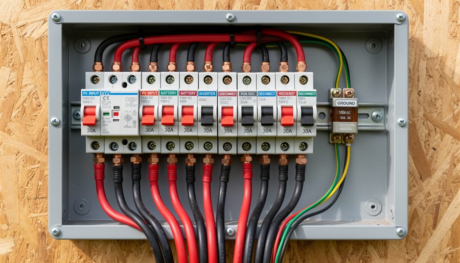
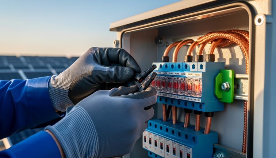
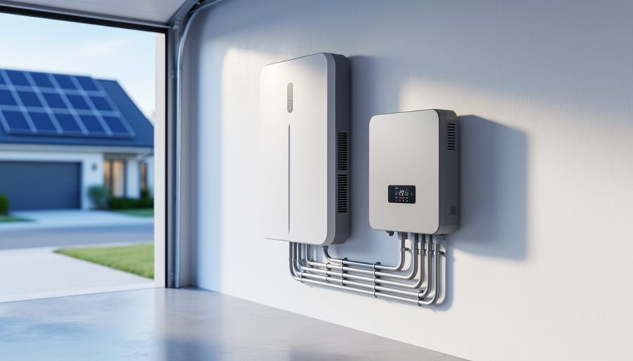
A close view of correctly installed DC protection hardware helps readers visualize what “rated circuit protection” looks like in a real DIY solar setup.
Why Low Voltage Systems Need Different Protection
Low voltage DC solar systems operate fundamentally differently from the AC circuits powering your home, and that difference demands specialized protection. The biggest surprise for most DIYers? For the same power output, DC systems pull significantly higher current. A 1200W load on household 120V AC draws 10 amps, but that same load on a 12V DC solar system pulls 100 amps, ten times as much. Higher current means more heat, greater stress on connections, and exponentially increased fire risk if something goes wrong.
Then there’s the arc problem. When you flip off an AC light switch, the current naturally crosses zero 120 times per second, making the arc extinguish easily. DC has no zero-crossing, once an arc starts, it wants to continue indefinitely. DC faults are harder to interrupt which is why you’ll sometimes see those scary videos of sustained DC arcs burning through metal. This persistent arc characteristic means DC-rated protection devices need completely different internal designs than their AC counterparts.
For off-grid cabins, van builds, and boat solar systems, this matters even more. You’re often working in confined spaces with limited ventilation, combustible materials nearby, and no fire department around the corner. A 12V or 24V system might seem “safe” because the voltage won’t shock you through dry skin, but the fault current from a large battery bank can easily exceed 1000 amps, enough to vaporize a wrench or ignite nearby wood in seconds.
Tools and Materials You’ll Need
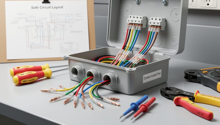
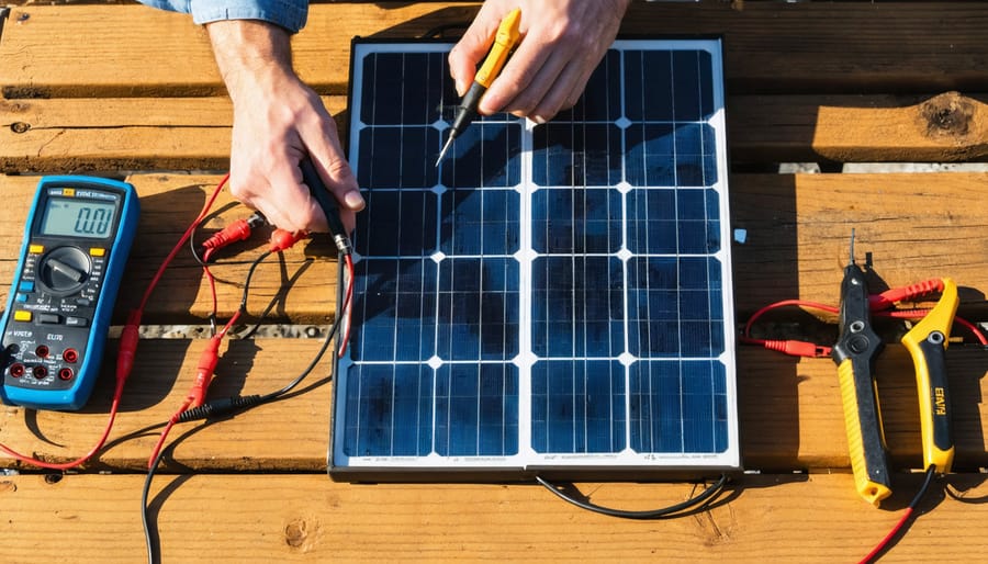
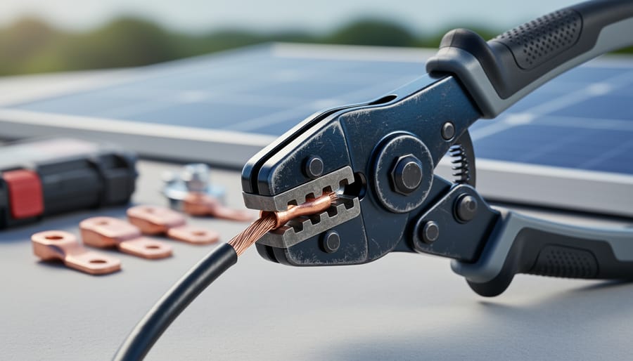
Tools and well-prepared wiring connections illustrate how proper installation supports safe current handling before you even choose protection sizes.
Before you start sizing circuit protection, gather everything you need to make accurate calculations and safe installations. Having the right tools on hand prevents mistakes and saves you from mid-project trips to the hardware store.
Here’s what you’ll need:
Wire ampacity chart showing current capacity for different gauge sizes and insulation types
Your system specifications including voltage (12V, 24V, or 48V) and maximum load currents
Calculator for determining current draw and sizing calculations, or use our Fuse Size Calculator for quick results
Digital multimeter to verify voltage and measure actual current draw
Circuit protection devices appropriate for your current range, such as ANL fuses (40-750A), MRBF fuses (25-300A), or DC-rated circuit breakers
You’ll also want your system schematic or a rough diagram showing where power flows from your panels through the charge controller, battery bank, and out to loads like your inverter. This visual reference helps you identify every circuit that needs protection and ensures you don’t miss critical connection points.
Keep a notebook handy to document your calculations. I learned this the hard way when I had to re-figure wire sizing six months after installation because I hadn’t written down my original math. Recording wire gauges, protection ratings, and the reasoning behind each choice creates a valuable reference for troubleshooting and future system modifications.
Critical Safety Warnings Before You Start
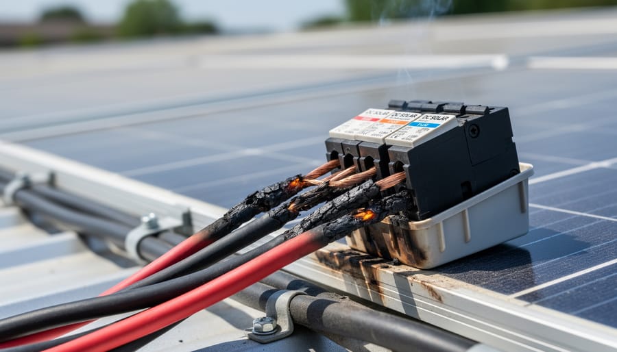
A visible cable damage scene conveys why undersized wiring and incorrect protection can overheat and create a fire hazard in DC solar circuits.
Before you grab your tools and start wiring, let’s talk about the safety stuff that could save your life, or at least your van from becoming a very expensive bonfire. I’ve seen too many DIY solar projects go sideways because someone skipped these warnings, and I’d rather you learn from others’ mistakes than your own.
Always disconnect your battery before working on any circuit. This sounds obvious, but it’s easy to convince yourself that “just adding one quick fuse” while live won’t hurt. DC current doesn’t forgive. Unlike AC household circuits that cross zero 120 times per second and naturally extinguish arcs, DC maintains constant voltage. If you create an arc, say, by dropping a wrench across terminals, it doesn’t stop. It sustains, it melts metal, and it can weld tools to busbars. I once watched a 10mm wrench disappear into molten metal in under three seconds across a 12V battery bank. The person holding it had second-degree burns.
Warning: Installing a larger fuse or breaker to stop nuisance tripping is like disabling your smoke detector because it’s annoying, the wire will overheat and ignite long before that oversized protection trips.
This brings up the most dangerous temptation in DIY electrical work: upsizing protection to “fix” a circuit that keeps tripping. If a 40A fuse blows repeatedly, the answer is never a 60A fuse. The answer is bigger wire or reduced load. Wire insulation typically ignites around 200°C, but a fuse sized at 150% of wire capacity might not trip until the wire’s already smoldering inside your wall or cabinet.
Finally, verify that every fuse and breaker you install is specifically rated for DC use at your system voltage. The interrupt rating, the device’s ability to safely extinguish a fault, matters enormously near batteries, where short-circuit currents can exceed 10,000 amps. An AC-rated breaker in a DC application can explode when it fails to interrupt that arc.
Step-by-Step: Sizing Circuit Protection for Your Solar System
Step 1: Calculate Your Maximum Current Draw
The first step in sizing your protection is knowing exactly how much current each circuit will actually draw. This is where the basic electrical relationship Watts = Volts × Amps becomes your foundation. Rearrange it to find current: Amps = Watts ÷ Volts.
Let’s walk through the common circuits in a DIY solar system. Say you’re running a 2000W inverter on a 12V battery bank. Divide 2000 watts by 12 volts, and you get roughly 167 amps during full load. In reality, factor in inverter inefficiency (typically 10-15%), so your actual draw is closer to 185-190 amps. This is your continuous current baseline.
For charge controller sizing, work both directions. On the input side from your panels, check the controller’s maximum PV input current rating from the spec sheet. On the output side feeding your batteries, a 40A MPPT controller on a 12V system can deliver up to 40 amps continuous. Use the controller’s rated output current, not calculated values, because the controller manages this electronically.
Battery bank connections demand special attention. If you’re wiring batteries in parallel, each connection point carries the total current demanded by all loads downstream. A system pulling 200 amps from the battery needs 200-amp capacity on every cable and protection device between the battery and distribution point.
Here’s the critical part: surge currents. Many devices pull significantly more when starting. Inverters can surge to 2-3 times their rated current for a few seconds during motor startup or heavy transients. While your protection doesn’t need to handle sustained surge, if you size too tight to the continuous rating, you’ll get nuisance tripping during normal operation. I typically add a 25% cushion to my calculated continuous current before moving to wire sizing. A Watts to Amps calculator simplifies these conversions, especially when you’re juggling multiple circuits.
Step 2: Size Your Wire Based on Current and Length
Once you know your maximum current draw, your next critical decision is wire size, and this must happen before you pick your protection device. Wire gauge determines how much current can safely flow without overheating, and undersizing wire is one of the most dangerous wire mistakes to avoid in any solar system.
Start with an ampacity chart specific to your wire type and installation method. For chassis wiring or free air routing common in van builds, you’ll use different ratings than wire bundled in conduit. The key rule: your wire must handle 125% of your continuous load current. If you calculated 150A maximum draw in Step 1, your wire needs 150 × 1.25 = 187.5A capacity minimum. This 80% continuous duty rule provides thermal headroom for real-world conditions.
But ampacity alone isn’t enough. You also need to check voltage drop, especially on longer runs. Even fat wire loses voltage over distance, and at 12V systems, a 3% drop means your inverter might see only 11.64V under load, potentially triggering low-voltage shutdowns. Use this formula: Voltage Drop = (2 × Length × Current × Resistance per foot) ÷ 1000. For most DIY solar circuits, aim to keep voltage drop under 3% for critical loads.
Here’s a practical example: that 150A inverter circuit on a 10-foot run needs 2/0 AWG wire minimum to meet both ampacity (230A in free air) and keep voltage drop to 2.1%. Going smaller saves money initially but costs you in heat, efficiency, and safety.
The Spheral Solar wire sizing calculator handles both calculations instantly and accounts for temperature derating, use it to verify your selections before buying cable.
Step 3: Select Protection Device Rating
Once you’ve sized your wire correctly, your protection device rating should match or fall slightly below the wire’s ampacity, never exceed it. This is the cardinal rule of circuit protection: the fuse or breaker exists to protect the wire from overheating, not to pass whatever current your load demands.
For most DIY solar applications, your protection device should be rated at or below the wire’s maximum ampacity from the charts you used in Step 2. Match OCPD to conductor ampacity as the foundational principle. If your 4 AWG wire is rated for 125 amps at your installation temperature, don’t install a 150A fuse thinking you’re giving yourself headroom, you’re creating a fire hazard.
Temperature derating matters here too. If your wire chart showed you needed to derate capacity due to high ambient temperatures (common in roof-mounted junction boxes or engine compartments), your protection device must reflect that derated capacity, not the wire’s theoretical maximum at 30°C.
Now for device selection. Different fuse types serve different current ranges, and choosing the right one keeps your system compact and cost-effective:
Blade fuses (ATO/ATC): 1-40A circuits. Perfect for small loads like USB ports, fans, or LED lighting circuits.
ANL fuses: 35-750A range. These are your workhorses for inverter and battery interconnect protection in most DIY systems. I use 300A ANLs for typical 3000W inverter setups.
MEGA/AMG fuses: 30-500A. Compact alternative to ANL, physically smaller, good where space is tight.
Class T fuses: 110-600A. Required for high-interrupt ratings near large battery banks. More expensive but necessary when short-circuit current could exceed 10,000A.
MRBF fuses: 30-300A. Compact, resettable-style terminals, popular in marine applications.
Breakers offer convenience, you can reset them instead of replacing fuses, but verify they’re DC-rated with adequate interrupt capacity for your application. Many cheap breakers are AC-only and will fail catastrophically in DC circuits, sometimes welding shut instead of opening.
Choose your fuse size first, then buy the holder rated for that fuse type. Never force a larger fuse into an undersized holder.
Step 4: Verify DC Interrupt Rating
Once you’ve picked the right size fuse or breaker, you need to confirm it can actually handle the worst-case scenario: a dead short. This is where interrupt rating comes in, and it’s particularly critical in low voltage DC solar systems because batteries can dump enormous current instantly.
The interrupt rating (also called breaking capacity) tells you the maximum short-circuit current the device can safely interrupt without exploding or welding shut. A fully charged 12V lithium battery bank can easily deliver 1,000 to 5,000 amps into a direct short. If your fuse or breaker isn’t rated for that level, it won’t open cleanly, it may arc internally, melt, or even catch fire while trying to break the circuit.
Here’s the dangerous part most DIYers miss: many common household circuit breakers are rated for AC only. AC current naturally crosses zero 120 times per second, which helps extinguish arcs. DC current is constant, so arcs sustain and grow. An AC-rated breaker might hold a DC arc instead of breaking it, creating a plasma torch inside your electrical panel. I’ve seen the aftermath, melted plastic, burned wires, and one charred breaker that fused permanently closed.
Always verify two things on your protection device: it must explicitly state “DC” in its ratings, and its interrupt rating must exceed your system’s potential short-circuit current. For most DIY solar systems with lithium batteries, look for devices rated at minimum 5,000A interrupt capacity at your system voltage. Quality ANL fuses, Class T fuses, and DC-rated breakers will clearly mark these specs. If the label only mentions AC voltage or doesn’t state an interrupt rating, don’t use it in your DC system.
Step 5: Position Protection Properly in Your System
Even perfectly sized protection won’t save you if it’s in the wrong spot. I learned this the hard way when a cable chafed through its insulation two feet from my battery bank, with the fuse mounted four feet away, that unprotected section turned into a welding arc before anything blew.
The golden rule: install your main battery protection within seven inches of the positive terminal. This isn’t arbitrary, it’s the NEC (National Electrical Code) standard that minimizes unprotected wire where a short circuit could start a fire before protection activates. For lithium batteries with their massive short-circuit potential, I go even tighter, typically three to four inches.
Your system needs protection at multiple strategic points, not just one massive fuse at the battery. Here’s where I place protection devices in every solar build:
At the battery positive terminal (within 7 inches): Main system fuse or breaker, sized for your largest load plus 25% margin. This protects the entire DC distribution system.
Before each inverter input: Dedicated protection sized specifically for that inverter’s maximum draw, even if you have main battery protection. This isolates faults and makes troubleshooting infinitely easier.
After your charge controller output: Protects the wire run to your battery and prevents backfeed during controller failures.
For each major branch circuit: Separate protection for lighting, appliances, and accessories sized to their specific wire gauge.
In my van builds, I use a Blue Sea fuse block for all the small loads (lights, USB, fans), each with its own protection, plus dedicated large fuses for the inverter and charge controller circuits. Redundancy isn’t paranoia, it’s insurance you’ll actually collect on.
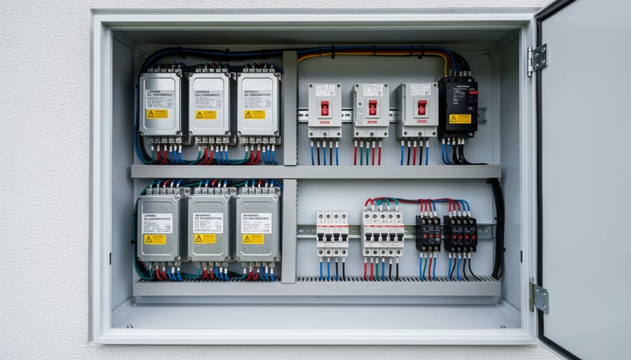
A live view of a neatly organized solar battery compartment helps readers picture protection devices installed in the right physical locations for reliable operation.
Common Protection Sizing Scenarios for DIY Solar
Battery to Inverter Protection
Let’s work through the most common high-current circuit in DIY solar systems: connecting your battery bank to an inverter.
Say you’ve got a 3000W pure sine wave inverter running on 12V. First, calculate maximum current: 3000W ÷ 12V = 250A continuous draw. But inverters aren’t 100% efficient, figure 90% at best, so actual battery draw hits around 277A. Add a 25% safety margin for surge currents when the inverter starts: 277A × 1.25 = 346A peak.
For 346A, you need serious wire. A 3-foot run from battery to inverter requires 4/0 AWG copper (good for 380A in chassis wiring applications). That’s about as thick as your thumb. Anything smaller and you’re asking for voltage sag, heat buildup, or both.
Now protection: your 4/0 wire handles 380A, so your fuse or breaker must protect it without nuisance tripping during normal 277A operation. A 300A ANL fuse or 300A Class T fuse fits perfectly here, high enough for normal operation, low enough to protect the wire if something shorts.
Mount that fuse within 7 inches of the battery positive terminal. I use a Blue Sea ANL fuse holder because it’s robust and I can see the fuse element. This single component prevents your expensive inverter cable from becoming a heating element during a fault.
Solar Panel to Charge Controller
Solar panel circuits need different protection than load circuits because the current source is limited by the panel itself. Your starting point is the panel’s short-circuit current (ISC) rating from the datasheet, this is the absolute maximum current the panel can produce, even if you dead-short the output. For a typical 100W 12V panel, ISC is around 6A; a 400W panel might be 11-12A.
Here’s the key difference: you size protection based on ISC multiplied by 1.25 to account for temperature coefficient variations and irradiance spikes. So that 400W panel with 11A ISC needs minimum 14A protection. If you’re wiring panels in parallel, add the ISC values together first, then multiply by 1.25. Three of those 400W panels in parallel would need 3 × 11A × 1.25 = 41A protection on the combined positive conductor.
Use our series/parallel calculator to map your array configuration, then check the total ISC before sizing your wire and breaker. The wire needs to handle that calculated current, and the breaker or fuse should be rated at or just above that 1.25× ISC value. Most charge controllers have internal protection, but a dedicated PV circuit breaker between the array and controller gives you a convenient disconnect point and protects the wire run itself, especially important for roof-mounted arrays where troubleshooting means climbing.
Verifying Your Circuit Protection Setup
Once you’ve installed your protection devices, take fifteen minutes to verify everything works as intended, this simple check catches mistakes before they become emergencies.
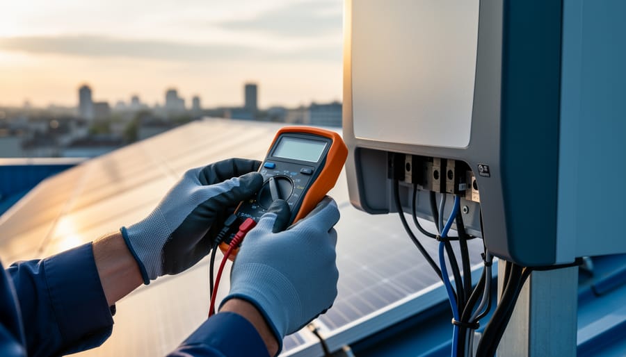
Start by powering up the system and running your typical loads. Use your multimeter to measure voltage at the battery terminals, then again at the load end of each protected circuit. Calculate the drop: if you’re seeing more than 3% loss (0.36V on a 12V system, 0.72V on 24V), either your wire is undersized or you have a poor connection somewhere. I learned this the hard way when an RV client complained about flickering lights, turned out the voltage drop revealed a loose busbar connection that would’ve eventually started a fire.
Next, run your verification checklist while everything’s operating:
All connections are tight and show no corrosion or discoloration
Voltage drop measures less than 3% under full load
No warmth detected at connection points after 30 minutes of operation
Protection devices don’t trip during normal loads (including inverter startup surge)
Protection DOES trip when you briefly create a known overcurrent condition
That last point is critical but often skipped. If you size your breaker correctly, it should hold steady during normal use but respond immediately to genuine faults. Test this by intentionally exceeding the rated current with a resistive load, the protection should activate. If it doesn’t, you’ve got the wrong device or a defective one.
Touch every connection point after the system’s been running. Warmth indicates resistance, and resistance means wasted energy heading toward failure.
What to Do Next: System Integration and Monitoring
You’ve sized your protection correctly and installed it, great work. But before you call it done, take thirty minutes to document what you built. Trust me, six months from now when something trips and you’re troubleshooting in the dark, you’ll thank yourself.
Grab a notebook or open a document and sketch your system. Mark every wire size, every fuse rating, every connection point. Include the calculations you just did, maximum current, wire gauge, and why you chose each protection device. When you upgrade later or help a friend with their build, this becomes your reference manual. I keep mine in a weatherproof sleeve zip-tied inside my electrical compartment.
Label everything with a permanent marker or label maker. “300A Main Battery Protection,” “40A Solar Controller Input,” “15A DC Lights Circuit”, whatever makes sense when you’re half-asleep and need to know what that fuse controls. Clear labels prevent the “guess and check” game that wastes time and risks mistakes.
Think about expansion now. If you might add panels or a bigger inverter later, note where you’d need to upsize wire and protection. Running new circuits is easier when you’ve planned the path.
For ongoing monitoring, check your system monthly at first. Feel connections for unexpected heat, look for discoloration around terminals, verify nothing’s tripping randomly. A quick multimeter check of voltage drop under load catches problems before they become fires.
Our community forum has dozens of members sharing their monitoring setups and expansion stories. Jump in, post your diagram, ask questions. We’ve all been exactly where you are now.
Getting your circuit protection right isn’t just good practice, it’s the foundation of a safe solar system. I’ve seen too many close calls from folks who treated fuses as an afterthought, and I promise you, the few extra minutes spent calculating proper protection are worth every second.
Remember the core sequence: calculate your load, size your wire generously, then match your protection to that wire capacity. Never reverse this order, and never upsize protection to stop nuisance tripping. If a properly sized fuse blows, it’s telling you something’s wrong, listen to it.
When I started building solar systems years ago, I’ll admit the electrical side intimidated me. But here’s what I’ve learned: you don’t need an engineering degree to do this safely. You just need to respect the fundamentals, take your time with the calculations, and double-check your work before flipping that switch.
You now have everything you need to protect your solar investment properly. Your system will be safer, more reliable, and you’ll sleep better knowing those electrons are flowing through protection that actually matches your setup. That’s real energy independence, not just generating power, but understanding and controlling it safely.
Frequently Asked Questions
Can I use automotive fuses in my solar system?
Automotive fuses can work for smaller circuits (under 30A), but they’re designed for 12V automotive applications with different arc interruption needs. For larger solar circuits, especially those near batteries, use properly rated DC fuses like ANL, MRBF, or Class T types that are designed to safely interrupt DC current and handle the sustained loads typical in solar systems.
Why can’t I just use the biggest fuse to avoid nuisance tripping?
Oversizing protection defeats its entire purpose, the fuse or breaker must protect your wire, not just your equipment. If you install a 200A fuse on wire rated for 100A, the wire becomes the fuse and will overheat, melt its insulation, and potentially start a fire before the protection device trips.
What’s the difference between fast-blow and slow-blow fuses?
Fast-blow fuses trip immediately when current exceeds their rating, while slow-blow (time-delay) fuses tolerate brief surge currents before tripping. Use slow-blow fuses for circuits with motors or inverters that draw high inrush current at startup, and fast-blow for sensitive electronics or circuits without surge loads.
Do I need circuit protection on both positive and negative wires?
You must have protection on the positive wire, as that’s where overcurrent occurs. Negative-side protection isn’t typically required in most DIY solar systems, though some choose to add it for extra safety or to meet specific standards, just ensure any negative-side protection is the same rating as the positive side so they trip together.
These questions come up constantly in the Spheral Solar community, and I get why. When you’re holding a 300A fuse in your hand for the first time, it feels excessive compared to the 15A breakers in your house. But remember, we’re dealing with different voltages here, that 3000W inverter pulling 250A at 12V would only draw about 25A at 120V AC.
One question I haven’t covered above but hear often: “Can I add protection later after I’ve already wired everything?” Technically yes, but please don’t. I’ve seen too many “temporary” unprotected setups become permanent because people get comfortable with them working. The time to install protection is before you energize the circuit for the first time. If you’ve already got an unprotected system running, treat adding protection as an urgent safety upgrade, disconnect everything, install proper protection sized according to the steps we’ve covered, then bring it back online. Your future self will thank you, and so will anyone who might have to deal with an electrical fire.
How useful was this post?
Click on a star to rate it!
Average rating 0 / 5. Vote count: 0
No votes so far! Be the first to rate this post.
We are sorry that this post was not useful for you!
Let us improve this post!
Tell us how we can improve this post?
charlesnoble
Here at Spheral Solar, I’m a hands-on solar power enthusiast, constantly exploring and experimenting with DIY solutions. I’m dedicated to sharing my discoveries, insights, and even the bumps I hit along the way, all in the pursuit of a more sustainable future.
Stop Tripping Your Solar System: Size Your 3-Phase… by Charlesnoble April 19, 2026 Calculate your three-phase breaker size by multiplying your load’s full-load current by 1.25, then selecting the next standard breaker rating above that value. For a 40-amp three-phase motor, you’d calculate 40 × 1.25 = 50 amps, meaning you need a 50-amp breaker minimum. Verify your voltage system first—208V, 240V, 480V,…
Wire Your Solar Panels Wrong and Watch Your… by Charlesnoble December 22, 2025 Match your wire gauge to your system’s amperage before making a single connection—undersized wire creates dangerous heat buildup and wastes the energy you worked hard to capture. For most residential 12V systems running under 30 amps, 10 AWG copper wire handles the load safely, but calculate your specific needs using…
Stop Burning Out Your Solar Gear: Why Electrical… by Charlesnoble February 22, 2026 Grab your multimeter and calculator—understanding electrical conversions transforms confusing numbers into actionable data for your solar setup. When I first started working with solar panels, I’d stare at spec sheets showing watts, amps, and volts, completely baffled about which numbers actually mattered for sizing my components. That confusion nearly led…
Stop Guessing Your Battery Power: The Conversion… by Charlesnoble October 28, 2025 Grab your battery specifications and check three numbers that matter: amp-hours (Ah) tells you total capacity like a fuel tank size, watt-hours (Wh) reveals actual energy storage accounting for voltage differences, and reserve capacity (RC) shows real-world runtime at a steady draw. These measurements aren’t interchangeable labels for the same…
Watts to Amps (W to A) Conversion Calculator by Charlesnoble March 23, 2023 What Is Amps? Amps is short for amperes. The ampere is the SI unit of electrical current, measuring the rate at which electrical charge flows through a circuit. One ampere equals one coulomb of charge passing through a conductor per second. In simpler terms, amps tell you how many electrons…
Why Your Solar Battery Dies Faster Than Expected… by Charlesnoble May 12, 2026 Calculate your required solar battery capacity by multiplying your daily energy consumption in kilowatt-hours by the number of days of autonomy you want. If your home uses 30 kWh daily and you want three days of backup power, you need 90 kWh of usable storage capacity. Remember that most batteries…
Subscribe for handpicked DIY projects, exclusive tips, and giveaways.
Low voltage circuit protection in DIY solar systems boils down to matching the right fuse or breaker to your wire size and expected current, not to the capacity of your battery bank or inverter. Most fires and equipment failures happen when people oversize protection devices, thinking bigger is safer, when the opposite is true. Your… Read more: How to Size Low Voltage Circuit Protection for Your DIY Solar System
Crimping 8-gauge wire correctly takes about 2 minutes per connection once you’ve got the hang of it, but those two minutes make the difference between a solar installation that lasts 25 years and one that fails in the first storm. An 8-gauge wire crimper is a heavy-duty hand tool designed to cold-forge lugs and terminals… Read more: How to Use an 8 Wire Crimper for Solar Panel and Battery Connections
Building a solar powered outdoor table takes about 8 to 12 hours and requires basic woodworking skills plus some familiarity with electrical connections. You’ll mount solar panels directly onto a custom-built or modified outdoor table, wire them to a charge controller and battery system housed underneath, and add USB ports or AC outlets for charging… Read more: How to Build a Solar Powered Outdoor Table for Your Camping Setup