Wire Your Motion Sensor Switch to Ignore False Triggers
Updated:
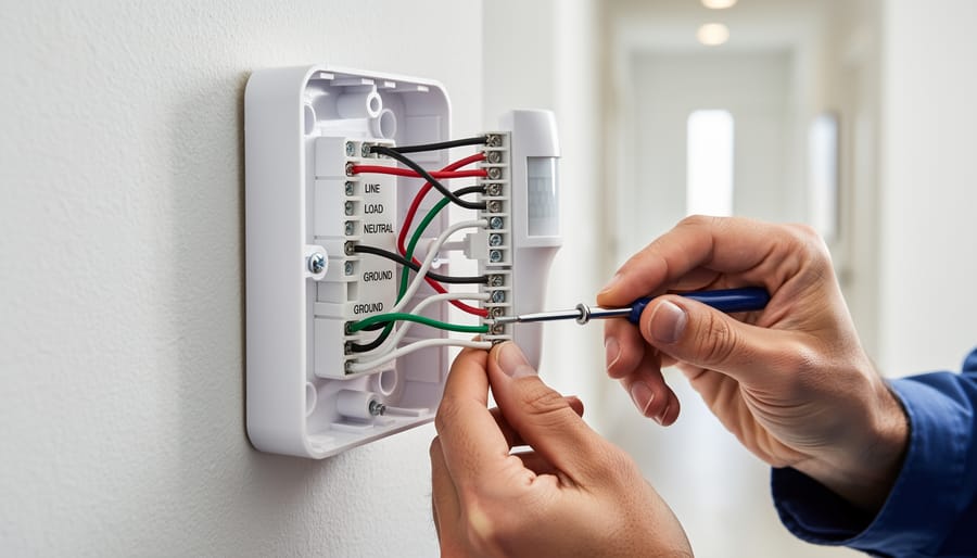
Wire your motion sensor switch by identifying the three critical connections: line (incoming power), load (outgoing to light fixture), and neutral. Connect the black wire from your power source to the sensor’s line terminal, the red or black load wire to your light fixture, and join all white neutral wires together with a wire nut. Ground connections go to the green or bare copper terminal—skip this step and you risk electrical shock.
Test your sensor’s detection zone before mounting permanently. Power on the circuit, adjust the sensor’s range dial to minimum, then gradually increase until it triggers at your desired distance. Most DIY installations fail because people mount first and adjust later, leading to awkward positioning and wasted effort.
Override false triggers by manipulating the time delay and sensitivity settings through simple dial adjustments. Turn sensitivity down if wind-blown branches constantly activate your light, or adjust the lux sensor threshold so daylight doesn’t interfere with detection. For solar shed lighting applications, this prevents unnecessary battery drain during peak sun hours.
Configure multiple sensors on one circuit by wiring them in parallel—connect all line wires together, all load wires together, and all neutrals together. This creates detection zones that work independently while controlling the same light fixture, perfect for L-shaped driveways or corner installations.
I learned this the hard way after my first sensor installation kept my garage light burning all night because a spider built a web across the lens. Simple wiring knowledge transforms frustrating equipment into reliable automation.
Why Motion Sensor Wiring Matters for Solar DIYers
The Battery Drain Problem Nobody Talks About
Here’s something I learned the hard way during my first solar motion light installation: a poorly wired motion sensor can silently drain your battery faster than you’d think. I watched my solar pathway lights dim within hours, and the culprit wasn’t the lights themselves, it was the constantly-active motion sensor.
Most motion sensors draw standby power 24/7, typically between 0.5 to 3 watts. That might sound tiny, but when you’re running on limited battery capacity from solar panels, it adds up fast. The real killer? False triggers from wind-blown branches, passing cars, or even temperature changes that activate your lights unnecessarily throughout the night.
When you’re configuring your motion sensor wiring, pay attention to the sensitivity adjustment wires. Many diagrams skip this detail, but connecting the sensitivity control properly can reduce false triggers by up to 70 percent in my experience. Also, consider adding a timer relay in your wiring setup. This simple addition prevents the sensor from operating during peak sunlight hours when detection isn’t needed anyway, preserving precious stored energy for nighttime use when it actually matters.
What ‘Manipulation’ Really Means
Let me clear up something important right from the start. When we talk about manipulating your motion sensor switch wiring, we’re not suggesting anything sketchy or unsafe. Think of it like tuning a guitar—you’re simply adjusting the setup to get the best performance.
In the context of motion sensor switches, manipulation means optimizing how your sensor responds to movement and controlling its behavior through proper wiring techniques. This might include adjusting sensitivity ranges, modifying time delays, or configuring multiple sensors to work together efficiently. For those of us running solar-powered systems, this optimization becomes especially valuable since we’re trying to squeeze every bit of efficiency from our battery banks.
I remember when I first installed motion sensors in my off-grid workshop. The default settings had lights blazing for five minutes after every trigger, draining my batteries faster than I could say “renewable energy.” By properly manipulating the wiring configuration—not bypassing anything, just optimizing the connections—I reduced unnecessary power consumption by nearly 40 percent.
What we’re definitely not talking about is disabling safety features, overriding manufacturer protections, or creating fire hazards. Good manipulation enhances functionality while maintaining all the safety protocols that keep your home and family protected. It’s about working smarter with the components you have, understanding the circuit logic, and making intentional choices about how everything connects together.
Understanding Your Motion Sensor’s Wire Layout
Understanding the wire layout and connections is essential for proper motion sensor installation and optimization.
The Three Essential Wires (And One Optional)
When I first started working with motion sensor switches in my off-grid cabin, I’ll admit the wiring intimidated me. But once I understood the basic wires involved, everything clicked into place. Let me break this down in the simplest way possible.
Every motion sensor switch uses three essential wires, plus one important safety wire. Think of them as the lifelines that make your sensor work properly.
The line wire, also called the “hot” wire, brings power from your electrical panel to the sensor. In North America, this wire is almost always black, though occasionally you’ll see red. This wire carries 120 volts, so it demands respect and careful handling.
The neutral wire completes the electrical circuit and is typically white or gray. Many DIYers get confused here because older light switches didn’t need a neutral wire, but modern motion sensors absolutely require one to power their electronic components, even when the light is off. This is especially crucial if you’re running sensors on a solar battery system, since they draw a tiny amount of standby power.
The load wire carries power from the sensor to your light fixture and is usually black or sometimes blue. When motion is detected, the sensor closes the circuit through this wire, turning on your lights.
Finally, the ground wire provides safety protection and is either bare copper or green. While technically optional in some older installations, I strongly recommend never skipping the ground wire. It protects you from potential electrical faults and gives peace of mind.
Reading Your Sensor’s Diagram
Before you grab your wire strippers, take a moment to really understand that diagram that came with your sensor. I learned this the hard way after miswiring a sensor in my workshop—let’s just say the lights had a mind of their own for a week!
Most manufacturer diagrams use universal symbols you’ll want to recognize. Look for the standard power lines (usually marked L or Line), neutral wires (N), load connections (where your light fixture connects), and ground symbols (that little tree-like icon). Three-wire sensors will show all of these, while two-wire models simplify things by eliminating the neutral.
Pay special attention to any colored wire indicators. Red typically means load, black is your hot line, white indicates neutral, and green or bare copper is always ground. However, don’t assume—some manufacturers get creative with their color coding.
Before diving in, check if your diagram shows voltage requirements (120V versus 240V) and whether it’s designed for AC or DC applications. This matters especially if you’re integrating motion sensors into a solar-powered system where you’re working with battery voltage. Many diagrams also include little notes about maximum wattage—crucial information that prevents overloading your sensor and keeps everything running smoothly.
Special Considerations for Solar-Powered Sensors
When I first started wiring motion sensors to my off-grid solar setup, I quickly learned that DC systems behave quite differently from standard AC household circuits. Solar-powered motion sensors typically operate on 12V or 24V DC power, drawn directly from your battery bank rather than grid power. This means you’ll need to check your sensor’s voltage requirements carefully – most AC motion sensors won’t work with DC power without a converter.
The wiring itself is simpler with DC systems. You’ll connect positive and negative wires directly from your charge controller or battery (through a fuse, always use a fuse!) to your sensor’s power input. Different motion sensor technologies have varying power draws, so calculate your daily consumption to ensure your battery capacity can handle overnight operation.
Battery integration is crucial for reliability. I recommend connecting your motion sensor circuit to your battery bank’s low-voltage disconnect to prevent deep discharge damage. Many solar enthusiasts also add a small dedicated battery just for security sensors, providing backup even during cloudy stretches. Remember, solar setups require reverse polarity protection – a simple diode can save your sensor from costly mistakes during installation.
Basic Wiring Diagram: Standard Installation
Tools and Materials You’ll Actually Need
Let me walk you through what you’ll need to tackle this project successfully. I learned the hard way that having the right tools from the start saves hours of frustration.
First, grab a wire stripper and cutter combo tool. You can find decent ones for under $15 at any hardware store, and they’re essential for cleanly removing insulation without damaging the copper wire. A voltage tester is non-negotiable for safety, ensuring your power is truly off before you work. These cost around $10 and could literally save your life.
You’ll need a screwdriver set with both flathead and Phillips options in various sizes since motion sensors use different screw types. Budget about $12 for a reliable set.
Wire nuts or terminal connectors are crucial for secure connections. Get an assorted pack for around $8. Don’t skimp here, loose connections cause most motion sensor failures.
For labeling your wires, electrical tape in different colors helps tremendously. Trust me, when you’re staring at a bundle of wires, knowing which is which prevents costly mistakes.
Optional but helpful: a headlamp keeps both hands free, especially in dim locations where motion sensors typically live. A basic multimeter, around $20, helps troubleshoot issues later.
Total investment runs about $60 to $75, tools you’ll use repeatedly for countless DIY projects.
Having the right tools and materials ready before starting prevents common wiring mistakes and ensures a safe installation.
The Connection Sequence That Prevents Problems
Getting your motion sensor switch wired in the right order isn’t just good practice—it’s what keeps you safe and your sensor working properly. I learned this the hard way years ago when I reversed two connections and spent an hour troubleshooting why my garage sensor kept the lights on permanently. Let me save you that frustration.
Always start by turning off the power at your circuit breaker. I can’t stress this enough—use a non-contact voltage tester to verify the power is actually off. Even experienced folks sometimes flip the wrong breaker.
Here’s the sequence that prevents headaches:
First, connect the ground wire. This is your safety foundation. Attach the bare copper or green wire from your motion sensor to the ground wire bundle in your electrical box using a wire nut. This protects against electrical faults before anything else gets connected.
Second, connect the neutral wire. Match white to white, securing them with a wire nut. This completes the return path for your circuit.
Third and finally, connect the hot wire. This is typically black, though sometimes red. Connect it to your power source’s hot wire. For solar-powered systems, this connects to your battery controller’s output.
The biggest mistake people make? Connecting hot wires first. This creates a live circuit before the safety ground is established, which is genuinely dangerous.
Another common error is mixing up the load and line wires. Your motion sensor has a line (incoming power) and load (outgoing to lights). Reversing these means your lights will either stay on constantly or never turn on at all. Check your sensor’s labeling carefully—most mark these clearly, but not always in obvious ways.
Advanced Wiring: Manipulating Sensor Behavior
Adding a Manual Override Switch
Sometimes you need lights to stay on regardless of motion—like during a movie night or when you’re working on a detailed project. Here’s where adding a manual override switch becomes incredibly handy.
I learned this the hard way when Charles and I were installing motion sensors in his workshop. He’d be soldering a circuit board, stay perfectly still for a few minutes, and suddenly be plunged into darkness. Not ideal! That’s when we added a simple 3-way switch to override motion sensor behavior whenever needed.
The wiring is straightforward. You’ll install a standard 3-way switch in series with your motion sensor. Connect the incoming hot wire to the common terminal of the 3-way switch. Then run a wire from one traveler terminal to your motion sensor’s line input. From the motion sensor’s load output, connect to your light fixture. The other traveler terminal connects directly to the light as well, creating a bypass path.
When the switch is in the “auto” position, electricity flows through the motion sensor, which controls the light based on movement. Flip it to “manual,” and power bypasses the sensor entirely, keeping lights on continuously—perfect for those marathon DIY sessions.
For solar-powered setups, this override is essential for battery conservation. You can manually shut off lights during low-battery conditions, overriding the sensor’s automatic operation. Just remember to label your switch positions clearly so everyone in the household knows which way is which.
Multiple Sensor Coordination
When you’re covering a large space like a long hallway or an open-plan living area, coordinating multiple motion sensors can save energy and prevent those annoying moments when lights flicker on and off as you move between zones. I learned this the hard way when I installed three sensors in my workshop without proper coordination—the lights would trigger in chaotic patterns, wasting precious battery power in my off-grid setup.
The key is wiring your sensors in parallel with proper zone planning. Start by mapping out your space and positioning sensors so their detection zones slightly overlap by about 10-15%. This creates seamless coverage without dead spots. When wiring multiple sensors to a single light circuit, connect all the hot wires from each sensor together, all neutrals together, and all load wires to your light fixture. This creates an “OR” logic—any sensor detecting motion will trigger the lights.
Here’s where it gets practical: adjust each sensor’s sensitivity and timer settings differently based on their location. For example, I set my doorway sensor to high sensitivity with a short timer (1 minute), while sensors deeper in the room use medium sensitivity with longer timers (3-5 minutes). This prevents false triggers from movement in adjacent rooms while maintaining coverage.
For solar-powered systems, this coordination is crucial. Multiple sensors working together efficiently means your lights only stay on as long as needed, preserving your battery reserves for cloudy days. Install a master bypass switch too—this lets you disable all sensors during extended work sessions without repeatedly waving your arms like you’re conducting an invisible orchestra.
Photocell Integration for Daylight Sensing
One of the smartest upgrades you can make to your motion sensor setup is adding a photocell, which detects ambient light levels. This simple addition ensures your lights only activate when motion is detected in darkness, preventing wasteful operation during daylight hours. I learned this lesson the hard way when my garage light kept triggering every morning as the sun streamed in, draining my solar battery system unnecessarily.
A photocell, also called a light-dependent resistor or LDR, works by changing its electrical resistance based on surrounding light. In bright conditions, it allows current to flow freely, essentially telling your motion sensor to stay off. When darkness falls, the resistance increases, enabling the motion detection circuit to operate normally.
To integrate a photocell into your motion sensor wiring, you’ll typically connect it in series with the power supply to the sensor itself. Most standalone photocells have two wires that splice into the hot wire feeding your motion sensor. When sufficient light is present, the photocell breaks the circuit, cutting power to the sensor. Some advanced motion sensors come with built-in photocells and adjustable sensitivity dials, making integration even easier.
For those running off-grid solar systems, this feature is particularly valuable. By preventing unnecessary activation during daylight, you can extend your battery runtime significantly. Many of my fellow DIY solar enthusiasts report 30-40 percent reductions in lighting energy consumption after adding photocell control. The component itself costs just a few dollars and takes minutes to install, making it one of the best energy-saving modifications available.
Integrating photocell sensors with motion detection ensures lights activate only when needed, maximizing solar battery efficiency.
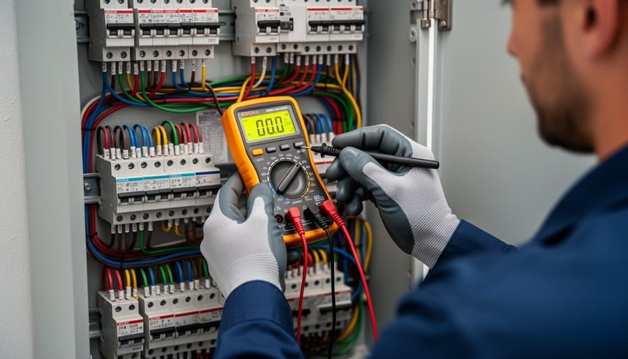
Troubleshooting Wiring Issues That Cause False Triggers
Systematic wire testing with a multimeter helps diagnose false trigger issues and connection problems quickly and safely.
When Your Sensor Won’t Stop Triggering
I’ve been there – standing in my garage at 2 AM, watching my motion sensor lights flicker on and off like a disco ball. It turns out that when your sensor won’t stop triggering, the culprit is often hiding in the wiring itself.
Start by checking for loose connections at your wire nuts or terminal screws. Even a slightly loose neutral wire can create voltage fluctuations that confuse your sensor’s detection circuitry. I learned this the hard way when a connection I thought was “tight enough” caused my outdoor sensor to false-trigger every time the wind blew. Give each connection a gentle tug – if anything moves, you’ve found your problem.
Incorrect load wiring is another common issue. If you’ve accidentally reversed your load and line connections, the sensor might continuously power cycle. Double-check that your line (incoming power) connects to the designated line terminals and your load (going to the light) connects to the load terminals. Your wiring diagram should clearly mark these.
For solar-powered or battery-backed systems, voltage fluctuations are particularly problematic. When your battery voltage drops or surges, the sensor’s microprocessor can misinterpret these changes as motion events. Adding a voltage regulator between your power source and sensor can smooth out these fluctuations, saving both your sanity and precious battery capacity.
If you’re still experiencing issues after checking these basics, it might be time to examine your sensor’s sensitivity settings and positioning rather than the wiring itself.
When Nothing Happens at All
When your motion sensor doesn’t respond at all, it’s time for some detective work. I remember Charles telling me about the time his outdoor solar sensor seemed completely dead, and he nearly replaced the whole unit before discovering one loose wire connection that fixed everything.
Start with the basics: use a multimeter to check for power at the source. Touch the probes to your hot and neutral wires (with the power on, so be careful). You should see around 120 volts for standard household circuits. No reading? The problem is upstream, likely at your circuit breaker or a tripped GFCI outlet.
Next, verify all your wire connections are secure. Turn off the power first, then gently tug each wire nut. Loose connections are sneaky culprits, especially in outdoor installations where temperature changes cause expansion and contraction.
For solar-powered motion sensors, check the battery voltage and solar panel output. Many issues that seem like wiring problems are actually power storage issues. If you’re dealing with solar lighting systems that won’t activate, the principles are similar to troubleshooting solar lights in general.
Finally, test the sensor itself by bypassing it temporarily with a direct wire connection. If your light works when bypassed, the sensor unit has failed and needs replacement.
Safety First: What Never to Do
Before we dive into the exciting world of motion sensor wiring, let’s talk about the stuff that really matters: keeping you safe. I learned this the hard way during my early solar tinkering days when I got a nasty shock from what I thought was a “harmless” 12V DC system. Trust me, even low-voltage systems deserve your respect.
First and foremost, never work on any wiring while the power is connected. This applies whether you’re dealing with standard household AC power or your solar DC system. Flip the breaker, disconnect the battery, and use a voltage tester to confirm everything is dead. I keep mine clipped to my belt as a constant reminder.
When working with outdoor motion sensors, never ignore waterproofing. Even sensors rated for outdoor use need properly sealed connections. Moisture infiltration is the number one killer of motion sensor systems, and it can create dangerous short circuits in your solar battery bank. Use waterproof junction boxes and silicone-filled wire nuts specifically designed for exterior applications.
Here’s something many DIYers overlook: never exceed the amperage rating of your motion sensor switch. If your sensor is rated for 5 amps, don’t push it to control a 10-amp load, even if it works initially. This is especially critical in solar DC systems where you might be tempted to run multiple LED fixtures through one sensor. Overloading causes heat buildup, which can melt connections or start fires.
Never mix up your positive and negative connections in DC systems. Unlike AC power, polarity matters tremendously with solar setups. Reversing these wires can instantly fry your motion sensor or, worse, damage your expensive charge controller.
Finally, never skip the ground wire connection, even in low-voltage applications. Proper grounding protects both you and your equipment from unexpected voltage spikes.
Understanding how to wire and manipulate your motion sensor switches puts real power in your hands. You’re no longer at the mercy of preset configurations or limited by off-the-shelf solutions. Whether you’re looking to conserve battery power in your solar setup, reduce false triggers in windy conditions, or simply create a lighting system that responds exactly how you need it to, you now have the knowledge to make it happen.
I’ve been tinkering with motion sensors in my off-grid workshop for years, and I can tell you there’s genuine satisfaction in getting a system dialed in just right. Every setup is unique, and that’s where the community comes in. Have you discovered a wiring trick that reduced your sensor’s power draw? Found a creative way to eliminate those annoying false triggers? We’d love to hear about it in the comments below. Your experience might be exactly what another DIYer needs to solve their challenge.
If you’re planning to integrate motion-activated lighting into a larger solar system, don’t forget to check out my solar calculator tool. It helps you size your panels and batteries correctly, accounting for the actual power consumption of sensors and lights, so you’re never left in the dark unexpectedly.
How useful was this post?
Click on a star to rate it!
Average rating 0 / 5. Vote count: 0
No votes so far! Be the first to rate this post.
We are sorry that this post was not useful for you!
Let us improve this post!
Tell us how we can improve this post?
charlesnoble
Here at Spheral Solar, I’m a hands-on solar power enthusiast, constantly exploring and experimenting with DIY solutions. I’m dedicated to sharing my discoveries, insights, and even the bumps I hit along the way, all in the pursuit of a more sustainable future.
Why Your Solar Area Lights Keep Failing (And How to… by Charlesnoble April 21, 2026 Mount your solar area lights where they’ll receive at least 6-8 hours of direct sunlight daily, avoiding shade from trees, buildings, or eaves that can cut charging efficiency by 70% or more. I learned this the hard way when my driveway lights barely lasted two hours each night until I…
How Ultrasonic Motion Sensors Can Supercharge Your… by Charlesnoble October 24, 2025 Ultrasonic motion sensors revolutionize home automation by detecting movement through high-frequency sound waves, offering precise detection ranges up to 25 feet without the false triggers common in traditional infrared sensors. These ingenious devices emit inaudible pulses at 40 kHz, measuring the time taken for echoes to return, and calculate exact…
Turn Any Chandelier Into a Solar-Powered Showpiece… by Charlesnoble February 17, 2026 Gather mason jars, solar garden lights, and a wire basket to create an elegant outdoor chandelier that requires zero electrical wiring and costs under $50. Pop the solar panels off inexpensive garden stakes, fit them into jar lids you’ve drilled holes through, and suspend everything from a chandelier frame you’ll…
How to Trick a Motion Sensor to Stay On by Charlesnoble September 14, 2023 There are many ways to trick a motion sensor of solar lights and security cameras to stay on. These include wrapping the sensor in aluminum foil to mimic motion, hanging shiny CDs that spin in the breeze, or pointing fans at the detector. This article provides a comprehensive guide to…
Your Hampton Bay Solar Light Stopped Working? Here’s… by Charlesnoble November 2, 2025 **Check the solar panel surface first** – dirt, leaves, or a thin film of grime blocks sunlight absorption and prevents charging. I learned this the hard way when my own Hampton Bay pathway lights died after just two weeks; a simple wipe with a damp cloth brought them back to…
Your Solar Light Won’t Turn On? Here’s Why (And How… by Charlesnoble November 10, 2025 Check your solar panel first—nine times out of ten, dirt, leaves, or shade are blocking the sunlight your fixture needs to charge. I learned this the hard way when my entire pathway lighting system “died” last fall, only to discover a thin film of pollen had cut charging efficiency by…
Subscribe for handpicked DIY projects, exclusive tips, and giveaways.
A J1772 solar charger combines a standard J1772 charging connector (the same Type 1 plug used by most North American EVs and electric bikes) with solar panels and battery components to create an off-grid or grid-supplemented charging system. You’ll need three core elements: solar panels (typically 400-800 watts for practical ebike charging), a battery storage… Read more: How to Choose a J1772 Solar Charger for Your Ebike: A Buying Guide
Installing a whole house ventilation system powered by solar takes about 6 to 8 hours for a moderately skilled DIYer and delivers continuous fresh air circulation without touching your electric bill. The core method involves mounting a solar panel on your roof to power an intake or exhaust fan, routing ductwork through your attic or… Read more: How to Install a Whole House Ventilation System Using Solar Power
Connecting your SolarEdge inverter to your home network via Ethernet cable takes about 15 minutes and gives you real-time access to your system’s performance data from any device with internet access. You’ll plug a standard Ethernet cable into the RJ45 port on your inverter (usually labeled “LAN” or “Ethernet”), run it to your router, and… Read more: How to Connect SolarEdge to Ethernet for Seamless System Monitoring


")

")

")
")
")

")

")
")


