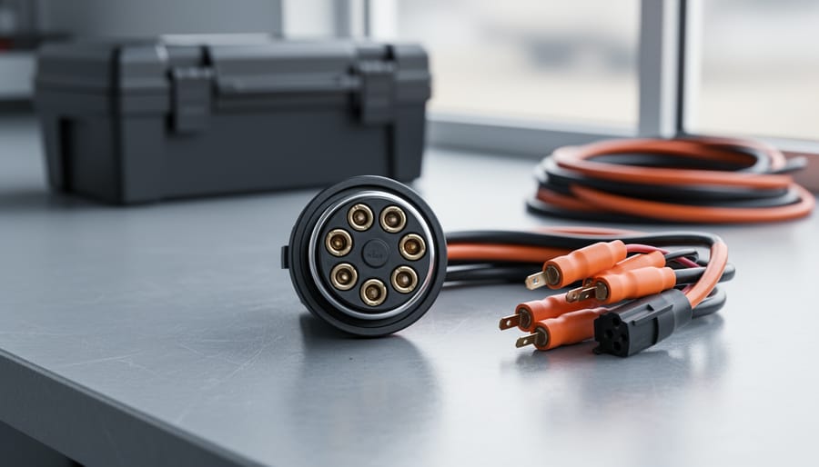
How to Wire a 7-Way RV Plug: Step-by-Step Diagram and Setup Guide
Updated:
Wiring a 7-pin RV plug correctly connects your tow vehicle to your trailer’s lights, brakes, and auxiliary power in about 45 minutes with basic hand tools and careful attention to the color-coded wire standard. The diagram follows a specific layout mandated by the RV Industry Association: each pin controls a distinct function, from left turn signals to electric brakes, and getting even one wire wrong can leave you without brake lights or, worse, damage your electrical system.
I’ve wired dozens of these connectors over the years, both on my own trailers and helping friends prepare their RVs for off-grid adventures. The job itself isn’t complicated, but it demands precision. One misplaced wire can mean a failed safety inspection or a dangerous situation on the highway when your brake lights don’t illuminate.
What makes this particularly relevant for solar-equipped RVs is that pin 4 on your 7-way connector supplies 12-volt auxiliary power. This same circuit often feeds your battery charging system when you’re plugged into your tow vehicle, which works alongside your solar setup to keep batteries topped off during travel. Understanding this wiring gives you better control over your entire electrical system.
This guide walks you through the complete process: identifying each wire and its corresponding pin, stripping and crimping connections properly, and testing everything before you hit the road. Whether you’re replacing a corroded plug or wiring a new trailer from scratch, you’ll have a reliable, safe connection that passes inspection and keeps your RV systems running exactly as they should.
Key Takeaway: The seven circuits are ground, tail/marker lights, left turn/brake, right turn/brake, electric brakes, reverse lights, and 12V battery charge line. Each circuit serves a specific safety or functional purpose, and mixing them up can disable critical systems like your brakes.
Understanding the 7-Way RV Plug Before You Start
Before you pick up your wire strippers, you need to understand exactly what you’re working with. A 7-way RV plug is the standard electrical connection between your tow vehicle and RV, carrying seven separate circuits that control everything from lighting to brake function. Unlike the basic 4-way plugs you might see on utility trailers, which only handle running lights and turn signals, the 7-way system manages more complex electrical needs specific to recreational vehicles.
Think of the 7-way plug as the communications hub between your truck and your RV. Each of those seven pins has a specific job. You’ve got a ground circuit that completes all the electrical loops, tail and marker lights that keep you visible at night, separate left and right turn signal circuits that also handle brake lights, an electric brake circuit that activates your RV’s braking system, reverse lights that illuminate when you’re backing up, and a 12V battery charge line that keeps your RV’s house battery topped up while you drive. If you’ve looked into the 7-pin connector explained resources before, you’ll recognize that “7-pin” and “7-way” refer to the same connector, different terminology, same essential function.
The integration with your RV’s electrical setup goes deeper than you might expect. That battery charge line doesn’t just keep your coach battery alive during travel, it connects directly to your RV’s 12V distribution system, which powers appliances, water pumps, and furnace fans when you’re off-grid. The electric brake circuit ties into a brake controller in your tow vehicle, sending precise voltage signals to activate magnetic brake assemblies inside your RV’s wheels. Get these connections wrong, and you’re not just dealing with a burned-out bulb, you could face brake failure or electrical fires. Understanding this interconnected system before you start wiring helps you appreciate why precision matters at every connection point.
Tools and Materials You’ll Need
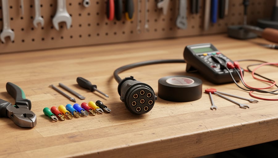
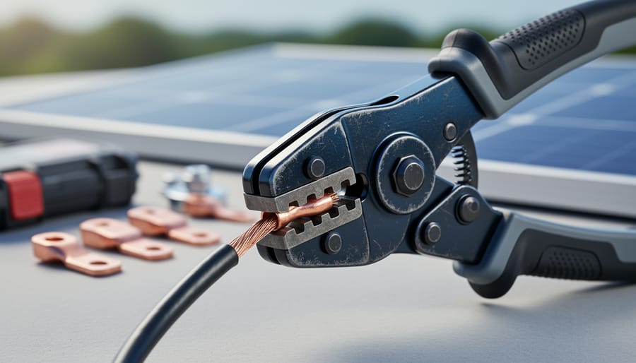
A close look at the 7-way RV plug and common wiring tools laid out on a bench helps readers visualize what they’ll be working with.
Getting the right tools and materials before you start makes this job infinitely easier and safer. I learned this the hard way on my first RV wiring project when I had to stop halfway through to make three trips to the hardware store. Don’t be like past-me.
Crimping tool, A ratcheting crimper ensures consistent, reliable connections
Multimeter, Digital is fine; you’ll use this for testing continuity and voltage
Heat gun or lighter, For shrinking heat-shrink tubing around connections
Diagonal cutters, For trimming wires to length
Screwdrivers, Flathead and Phillips for the plug housing screws
Socket wrench set, For removing battery terminals safely
Wire brush, To clean corrosion from existing connections
Required Materials:
7-way RV plug, Buy quality; cheap plugs corrode fast and fail when you need them most
Trailer wire cable, Get the proper gauge for each circuit (typically 14-gauge for lights, 10-gauge for battery charging)
Heat shrink tubing, Various sizes to fit your wire gauges
Wire connectors or solder, Crimp connectors are easier for beginners; solder creates stronger bonds
Electrical tape, For additional moisture protection
Dielectric grease, Prevents corrosion in the plug connections
Cable clamps and conduit, To protect and secure wiring along its route
Don’t cheap out on the plug itself or the wire quality. A failing connection at highway speed isn’t just inconvenient; it’s dangerous. I use marine-grade components whenever possible because they’re built to resist moisture and vibration, both of which your RV will encounter plenty of.
Safety First: Critical Warnings Before Wiring
Before you touch a single wire, understand that improper 7-way plug wiring can cause serious problems, from a blown fuse to a trailer fire or complete brake failure while you’re towing. I’ve seen RVs where the electrical system keeps failing because someone rushed through the wiring without taking basic precautions. Don’t let that be you.
Warning: Always disconnect your RV battery before starting any wiring work, and never cross or reverse the brake circuit wires, doing so can disable your trailer brakes completely.
Work in a dry environment, preferably indoors or under cover. Moisture and electrical work don’t mix, and corrosion starts the moment water contacts exposed connections. Keep your workspace organized so you don’t accidentally swap wires or lose track of which circuit you’re working on.
This isn’t a project to rush through on a Sunday afternoon before a trip. Each connection matters. A reversed turn signal wire might just mean your blinker doesn’t work, but a shorted battery charge line can fry your RV’s electrical components or start a fire. Take your time, double-check every connection against the diagram, and verify your work before reconnecting power. The hour you spend being careful now will save you days of troubleshooting, or worse, down the road.
The 7-Way RV Plug Wiring Diagram Explained
The heart of any 7-way plug installation is understanding the diagram itself. Picture the plug face-on, as if you’re looking directly at the socket or connector. The seven pins are arranged in a specific circular pattern with one pin at the center. This isn’t random: the layout prevents you from plugging things in incorrectly and ensures each circuit lands where it should.
Let me break down what each pin does. The center pin is your ground connection, the foundation everything else relies on. Moving clockwise from the top (12 o’clock position), you’ll typically find the left turn signal, electric brakes, battery charge line, right turn signal, tail and running lights, and reverse lights. Each circuit serves a distinct function, and mixing them up can mean anything from lights that don’t work to brakes that fail when you need them most.
Now here’s where it gets a bit tricky: wire colors. The industry standard calls for white (ground), yellow (left turn), blue (brakes), black (battery charge), green (right turn), brown (tail lights), and purple (reverse lights). I learned the hard way on my first RV project that not every manufacturer follows this convention religiously. Some trailers use red for battery charge instead of black, or orange for one of the circuits. Always verify against your specific RV’s documentation rather than assuming the colors match what you expect.
When you look at a wiring diagram, you’ll usually see a circular representation with numbered or color-coded positions. The key is understanding the relationship between physical pin position and wire function. I keep a laminated reference card in my tool kit that shows both the standard layout and the alternate color schemes I’ve encountered. It has saved me from rewiring jobs more than once.
The most critical circuits to get right are the brakes and ground. The brake circuit typically needs a heavier gauge wire (12 or 10 AWG) because it carries higher current to activate your trailer brakes. The battery charge line also needs substantial gauge to effectively charge your RV batteries while driving. Getting these wrong isn’t just inconvenient, it’s dangerous. Take time with this diagram reference before you touch a single wire.
Step-by-Step Wiring Process
Step 1: Prepare Your Work Area and Disconnect Power
Before touching any wires, disconnect your RV’s battery by removing the negative terminal first, then the positive. This eliminates shock risk and prevents accidental shorts. If your RV has a battery disconnect switch, flip it to “off” and still physically disconnect at least one terminal, I learned this after a “disconnected” battery still had enough residual power to give me a memorable jolt.
Choose a dry, well-lit workspace with room to spread out your diagram, tools, and materials within easy reach. Lay everything on a tarp or workbench in the order you’ll need it. Use your multimeter to confirm zero voltage at the plug location before proceeding. Double-check by testing the connection points where you’ll be working, don’t assume the disconnect worked. This two-minute verification has saved me from several close calls.
Step 2: Strip and Prepare the Wires
Start by measuring twice and cutting once, you’ll need about 6 inches of wire extending beyond the plug housing for comfortable work, but not so much that you create excess slack to manage later. Use quality wire strippers adjusted to match your wire gauge (typically 14-gauge for most circuits, though 10 or 12-gauge for the battery charge line). Strip about half an inch of insulation from each wire end, exposing clean copper without nicking the metal strands underneath.
If you accidentally nick the wire, cut it back and strip again. Damaged strands create weak points that can fail from vibration on the road. For heavier gauge wires, make multiple light passes with the stripper rather than one aggressive squeeze, this prevents strand damage that’s harder to see but reduces current capacity.
Lay out your stripped wires on your work surface, grouping them by function: ground together, turn signals together, and so on. This organization prevents mistakes when you’re ready to connect. Twist the exposed copper strands tightly clockwise with your fingers to create a neat, compact end that won’t fray when inserting into terminals.
Step 3: Match Wires to the Diagram
Now comes the crucial part where you’ll match each wire from your RV to the correct pin on the 7-way plug. Lay your stripped wires next to the plug and reference the diagram you studied earlier.
Start by identifying each wire’s function rather than relying solely on color. If you’re lucky, your RV follows standard color coding and everything matches the diagram perfectly. More often, you’ll find variations. Charles remembers a trailer where the manufacturer used all white wires with colored tape, confusing until he traced each one back to its source.
Use a multimeter to verify each wire’s function before connecting. Trace the ground wire back to the frame, the brake wire to the brake controller, and so on. Mark each wire with tape if needed, writing the pin number directly on the tape.
Double-check everything. Mixing up the brake and turn signal wires won’t just fail an inspection, it creates a dangerous situation where your trailer signals incorrectly or brakes fail when you need them most.
Step 4: Crimp or Solder Connections
Once you’ve matched each wire to its correct pin, it’s time to make the actual electrical connection. You have two solid options here: crimping or soldering. Both work if done correctly, but they require different techniques.
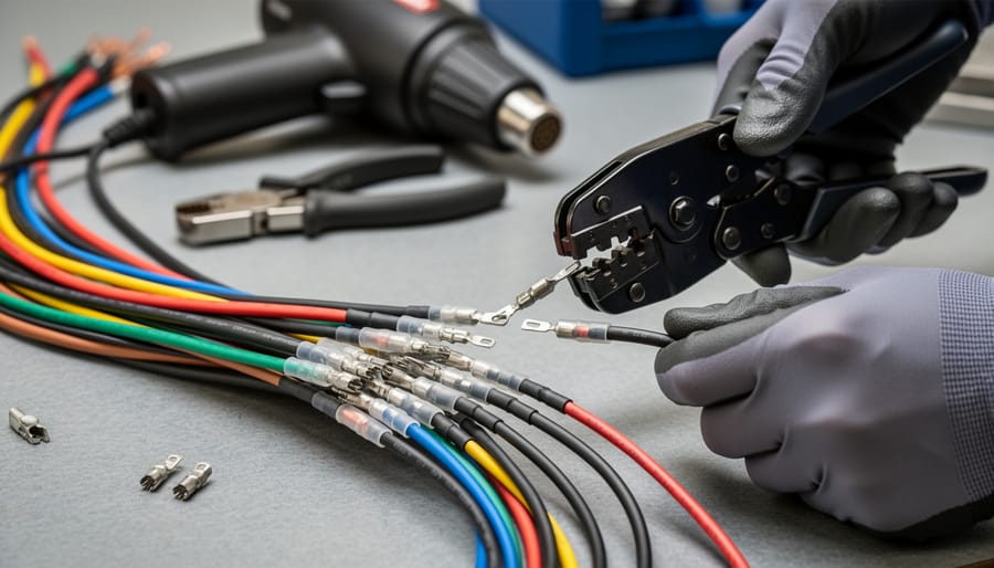
Crimping is faster and doesn’t involve heat near your wires. Use a quality ratcheting crimper, not the cheap pliers-style tool, and slide the appropriate connector onto your stripped wire. Insert the wire fully into the barrel, then crimp firmly until the tool releases. Give each connection a gentle tug test. If the wire pulls free, redo it.
Soldering creates the most reliable connection. I prefer this method for anything carrying significant current like the battery charge circuit. Heat the wire and connector together, then apply solder until it flows into the connection. Let it cool naturally without blowing on it.
Regardless of method, slide heat shrink tubing over every connection before you crimp or solder, I forget this constantly and have to redo connections. After the connection cools, heat the tubing with a heat gun until it shrinks tight. This waterproofs the joint and prevents the bare metal from corroding on the road.
Hands-on wiring work shows how secure crimped and heat-shrunk connections look when done properly.
Step 5: Secure Wires to the Plug Housing
Once you’ve made solid connections, it’s time to secure everything in the plug housing. This step prevents your hard work from unraveling the first time you hit a pothole.
Start by carefully feeding each wire into its designated terminal slot in the 7-way connector body. Don’t force them, if a wire doesn’t slide in smoothly, check that your crimp or solder joint isn’t too large for the opening. Each wire should sit flush against the back of its terminal pin.
Now tighten the set screws on each terminal. Use a screwdriver that fits properly, a loose fit can strip the screw heads. Snug them down firmly, but don’t overtighten to the point where you crack the plastic housing or damage the wire insulation. Give each wire a gentle tug after tightening to confirm it’s locked in place.
Pay special attention to the strain relief mechanism. Most quality 7-way plugs have a cable clamp or grommet where the main wire bundle enters the housing. Secure this properly so that road vibration and the inevitable tugging during hookup transfers stress to the housing, not your individual connections. I learned this the hard way when a poorly secured ground wire worked loose during a cross-country trip, not fun troubleshooting in a campground parking lot.
Step 6: Route and Protect the Wiring
Once your connections are solid, the real work is protecting those wires from the punishment they’ll take on the road. I learned this the hard way when a poorly-routed wire rubbed against a frame member for 500 miles and nearly shorted out my entire lighting system.
Run your wire bundle from the 7-way plug toward the RV’s main electrical panel using the cleanest path possible. Stay away from the exhaust system, suspension components, and anything that moves or generates heat. Split loom tubing or flexible conduit is your friend here, slide the entire wire bundle through it before routing. This protects against abrasion, moisture, and UV damage.
Secure the conduit every 12 to 18 inches with appropriate clamps or zip ties. Don’t just use standard plastic zip ties on exposed areas; they’ll crack and fail within a year. Invest in UV-resistant ties or proper conduit clamps that bolt to the frame. Leave a slight service loop, about six inches of slack, near the plug itself so the wires can flex when you connect and disconnect without pulling on the terminals.
Check your routing for pinch points where the wire might get crushed when the suspension compresses or where it could contact sharp metal edges. Add rubber grommets anywhere the conduit passes through a hole in metal. This extra fifteen minutes of careful routing will save you from roadside electrical failures later.
Testing and Verification: Making Sure Everything Works
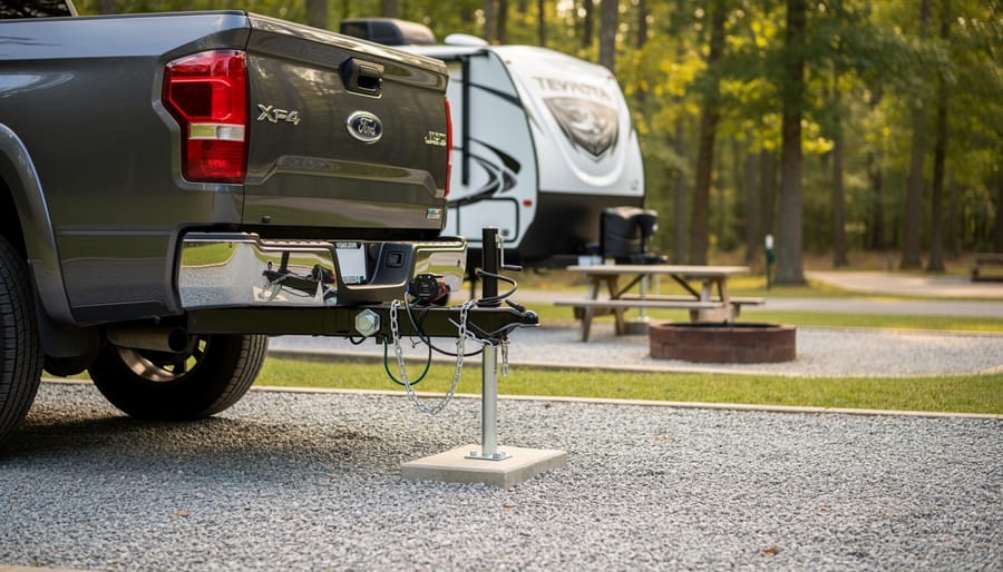
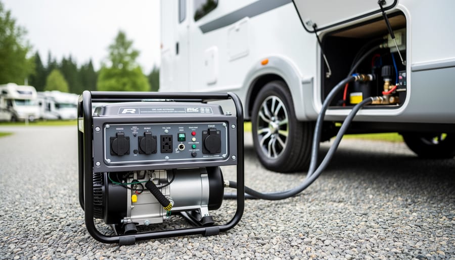
A connected tow setup at a campsite illustrates what a correctly wired 7-way plug setup looks like in real-world travel conditions.
Once you’ve completed the physical wiring, resist the urge to immediately button everything up. Testing each circuit now, while you still have easy access to connections, can save you hours of frustration later. I learned this lesson the hard way when I thought everything looked good, reassembled my trailer connector, and discovered on the highway that my brake lights weren’t working. Not fun.
Start by reconnecting your RV battery and ensuring your tow vehicle is hooked up. Before you even turn on any lights, use a multimeter set to continuity mode to verify each wire has a solid connection from the plug pins through to their destinations. Touch one probe to a pin on the plug and the other to the corresponding wire terminal inside the RV. A beep or zero-ohms reading confirms continuity. No reading means you’ve got a break somewhere or a loose connection that needs fixing.
For a thorough verification, test each circuit systematically in this order:
Ground circuit (white wire): Check continuity between the ground pin and the trailer frame. This is your foundation for everything else.
Running lights (brown wire): Turn on your tow vehicle’s parking lights and verify the RV marker lights illuminate.
Left turn/brake (yellow wire): Activate the left turn signal, then the brake pedal separately. Watch for the corresponding lights.
Right turn/brake (green wire): Repeat the same process for the right side.
Electric brakes (blue wire): With the brake controller activated, you should hear the trailer brakes engage. Use a brake controller tester or simply feel for resistance when manually moving the RV.
Reverse lights (black wire): Shift into reverse and confirm the backup lights work.
Battery charge line (red wire): Use your multimeter to check for 12V DC at the battery when the tow vehicle is running. This circuit charges your RV battery while driving.
A dedicated 7-way plug tester makes this process even faster. These inexpensive tools plug into your connector and light up LEDs for each working circuit when you activate the corresponding function on your tow vehicle. They won’t test brake function or battery charging voltage, but they quickly verify the basic light circuits.
If a circuit fails, start at the plug and work backward. Check for loose pins, verify your wire gauge is adequate for the circuit’s amperage (especially critical for the brake and battery charge lines), and inspect for damaged insulation or pinched wires. Nine times out of ten, the problem is a connection that looked fine but wasn’t quite tight enough.
Integrating Your 7-Way Plug with Solar and Battery Systems
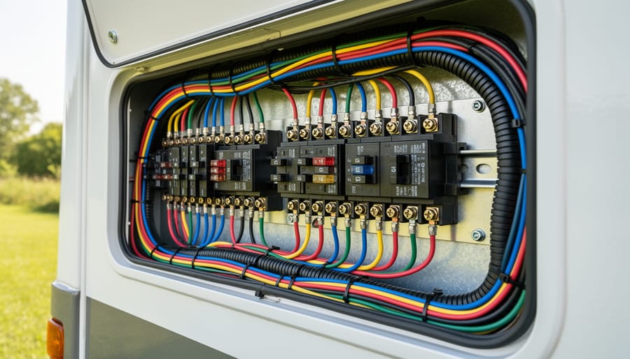
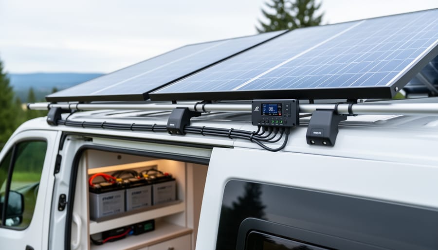
Seeing the tidy routing inside an RV electrical compartment reinforces how protected wiring and clean connections support safe operation.
When you wire a 7-way RV plug, that pin 4 circuit (typically the 12V battery charge line) can work alongside your solar setup, but only if you understand how the two charging sources interact. Your tow vehicle sends charging voltage through this wire while you’re driving, and your solar panels do the same when the sun’s out. The good news? They can coexist peacefully. The bad news? Without proper planning, you can create voltage conflicts or even damage your batteries.
I learned this the hard way during my first solar RV build. I’d installed a beautiful 400-watt solar array with a quality MPPT controller, then connected the 7-way plug without thinking through the charging logic. The first long drive, my solar controller kept switching between bulk and float charging erratically because it was seeing voltage from the alternator. It didn’t hurt anything, but it was inefficient and concerning.
The solution is isolation. Modern solar charge controllers handle multiple charging sources well, but your tow vehicle’s alternator doesn’t know about your solar system. If you’re running a basic setup where the 7-way charge line connects directly to your battery, make sure your solar controller can handle the voltage spikes from alternator charging (most quality controllers can). For more sophisticated systems, especially with lithium batteries, consider adding a DC-to-DC charger between your tow vehicle and battery bank. This regulates the charging voltage properly and prevents conflicts.
Check your DC-to-DC charger sizing based on your alternator output and battery capacity. I use a 40-amp unit in my rig, which handles both the solar input and tow vehicle charging without any voltage fights. Wire the 7-way charge line to the DC-to-DC charger input instead of directly to the battery, and let the charger manage the rest.
One practical tip: label your connections clearly. Future you (or a mechanic) will appreciate knowing which wire comes from solar, which from the 7-way plug, and where they meet at the battery or charge controller.
Common Wiring Mistakes and How to Avoid Them
I’ve seen more than my share of 7-way plug problems, and most trace back to the same handful of mistakes. The most common error is reversing the brake controller and turn signal wires, they’re often adjacent pins, and in poor lighting or when you’re rushing, it’s easy to swap them. The consequence isn’t just non-functional turn signals; you can send 12V directly to your brake controller when you activate a turn signal, potentially damaging the controller and leaving you with no trailer brakes when you actually need them. Always triple-check these connections against your diagram before you secure anything.
Another frequent issue is using wire that’s too thin for the battery charge circuit. Some DIYers grab whatever 16-gauge wire is lying around, but the charge line should be at least 12-gauge (preferably 10-gauge) to handle the current without excessive voltage drop. Undersized wire heats up, wastes charging capacity, and can contribute to situations where your battery dies overnight despite being connected to the tow vehicle all day. Similarly, poor ground connections cause all sorts of erratic behavior, dim lights, intermittent brake function, and electrical gremlins that are maddening to diagnose. Your ground wire must make solid contact with clean, bare metal on both the vehicle frame and the RV chassis, and it needs to be the same gauge as your heaviest power wire.
Tip: Apply dielectric grease to every pin and connection inside the plug housing before final assembly, it prevents corrosion and ensures reliable contact even in wet conditions.
The mistake I see people completely forget is weatherproofing. You’ve made perfect electrical connections, but if moisture gets in, corrosion will destroy them within months. Use heat shrink tubing on every wire joint, seal the back of the plug housing properly, and install a weather cap on the vehicle-side receptacle when not towing. Prevention is simple; fixing corroded connections on the side of the road in the rain is not.
Maintenance and Troubleshooting Your 7-Way Connection
Your 7-way connection isn’t a set-it-and-forget-it part, it takes a beating from road grime, moisture, and temperature swings, so a little regular care goes a long way. Every few months, pull the plug apart and inspect the pins and socket for corrosion, which looks like white or greenish powder on the metal. Clean both sides with a wire brush or fine sandpaper, then spray with electrical contact cleaner and let it dry completely before reconnecting. Check that the ground wire is still tight; a loose ground causes all sorts of phantom electrical gremlins.
If your running lights suddenly go dim or your electric brakes feel mushy, start by wiggling the plug while someone watches the lights, intermittent connection often means worn pins or a cracked housing. A voltmeter confirms whether each circuit is actually carrying power; no voltage on a pin means a break somewhere between the truck and the RV. Inspect the wiring where it enters the plug housing and along any exposed runs, vibration can fray insulation or loosen crimps over time. If you’re seeing repeated issues, revisit how you wire them right during initial setup, because poor crimps or inadequate strain relief will eventually fail.
Apply dielectric grease to the pins before every trip; it repels water and prevents corrosion. Replace the entire plug if the plastic housing cracks or the pins no longer grip firmly, trying to limp along with a degraded connector is how you end up stranded with no brake lights on the highway.
Frequently Asked Questions
The questions below address the most common concerns I hear from RVers tackling this project for the first time.
Can I use different wire colors than the standard diagram shows?
Yes, you can use different colors, but you must carefully label each wire and maintain consistent connections on both ends. The color coding is a convenience, not a requirement, but using standard colors helps anyone troubleshooting later and reduces your chance of error during installation.
What if my RV has a different plug type?
Older RVs may have 4-way or 6-way plugs, while some European models use 13-pin connectors. You’ll need an adapter or complete rewiring to match systems. For safety and full functionality including brake control and battery charging, upgrading to a 7-way is usually worth the effort.
Do I need special wire for the brake circuit?
The brake signal wire doesn’t require special wire, but the battery charge circuit needs at least 10-gauge wire to handle charging current without overheating. Using undersized wire here creates a fire risk and won’t charge your RV battery effectively.
Can I wire this myself or should I hire an electrician?
If you’re comfortable with basic electrical work, can follow a diagram carefully, and have the right tools, this is a manageable DIY project. However, if you’re uncertain about any step or the consequences of a mistake worry you, hiring a qualified RV technician gives you peace of mind and typically costs between two and four hundred dollars.
How does this wiring affect my solar system?
The 12V charge line in your 7-way plug can work alongside your solar panels to charge your house batteries while driving. Make sure your solar charge controller can handle multiple charging sources, and consider installing a battery isolator to prevent your tow vehicle from draining your RV batteries when parked.
These answers reflect real-world scenarios I’ve encountered and troubleshot over years of working with RV electrical systems. The brake wire gauge question is particularly important because I’ve seen melted insulation from people using 16-gauge wire on that circuit, thinking it was just a signal wire like the turn signals.
Wiring a 7-way RV plug correctly isn’t just about convenience, it’s fundamental to your safety on the road and the reliable operation of every electrical appliance in your RV. From your brake lights to your refrigerator, from battery charging to solar system integration, this single connection carries critical circuits that keep you and your family safe while traveling.
The good news? This is absolutely a project you can tackle yourself. With the diagram as your guide, the right tools in hand, and a methodical approach to each step, you’ll have a professional-quality connection that’ll serve you reliably for years. I’ve guided dozens of RV owners through this process, and the sense of accomplishment when you hook up, test, and everything works perfectly is genuinely rewarding.
If you ran into challenges or discovered helpful tricks during your wiring project, we’d love to hear about it in the Spheral Solar community. Your experience might help the next person who’s staring at a bundle of wires wondering where to start. And if you’re interested in maximizing your RV’s electrical independence, check out our guides on solar panel integration, because once you’ve mastered this connection, a solar setup is the natural next step toward true off-grid freedom.
How useful was this post?
Click on a star to rate it!
Average rating 0 / 5. Vote count: 0
No votes so far! Be the first to rate this post.
We are sorry that this post was not useful for you!
Let us improve this post!
Tell us how we can improve this post?
charlesnoble
Here at Spheral Solar, I’m a hands-on solar power enthusiast, constantly exploring and experimenting with DIY solutions. I’m dedicated to sharing my discoveries, insights, and even the bumps I hit along the way, all in the pursuit of a more sustainable future.
Why Is My Solar Inverter Showing Arc Fault E050?… by Charlesnoble September 9, 2026 Nine times out of ten, an E050 arc fault error on your solar inverter means a loose connection somewhere in your DC wiring. Before you panic or call an expensive technician, check every MC4 connector between your panels and inverter. A single connection that wasn’t snapped fully closed or has…
How to Install a Solar Heating System for Your… by Charlesnoble August 25, 2026 You can heat your inground pool with solar panels mounted on your roof, garage, or ground rack, capturing free energy from the sun and extending your swim season by months while slashing heating costs to nearly zero. A properly sized solar heating system circulates pool water through black collector panels…
6 Best Solar Spot Lights of 2026, Tested and Reviewed by Charlesnoble August 8, 2026 After testing dozens of solar spotlights in real-world conditions throughout 2026, the AloftSun Solar Motion Sensor Outdoor Lights emerged as the top overall choice for most homeowners, thanks to its reliable performance and versatility across different landscape lighting scenarios. But picking the right solar spotlight depends entirely on what you’re…
How to Install a Whole House Ventilation System… by Charlesnoble July 12, 2026 Installing a whole house ventilation system powered by solar takes about 6 to 8 hours for a moderately skilled DIYer and delivers continuous fresh air circulation without touching your electric bill. The core method involves mounting a solar panel on your roof to power an intake or exhaust fan, routing…
How to Use an 8 Wire Crimper for Solar Panel and… by Charlesnoble September 24, 2026 Crimping 8-gauge wire correctly takes about 2 minutes per connection once you’ve got the hang of it, but those two minutes make the difference between a solar installation that lasts 25 years and one that fails in the first storm. An 8-gauge wire crimper is a heavy-duty hand tool designed…
Why Two Solar Panels Beat One Every Time (Parallel… by Charlesnoble June 22, 2026 Connect your panels to a charge controller or battery system by running positive terminals to positive and negative to negative. This parallel configuration doubles your available current (amperage) while keeping voltage the same, which is exactly what you need when your system demands more power than a single panel can…
Subscribe for handpicked DIY projects, exclusive tips, and giveaways.
Nine times out of ten, an RV generator that won’t start has a stale fuel problem. If your generator hasn’t run in more than 30 days, degraded gasoline is likely gumming up the carburetor and preventing ignition. Before you panic or call for expensive roadside service, try this: turn on the generator’s fuel valve (if… Read more: RV Generator Troubleshooting: Common Problems and How to Fix Them
A 5kW solar system occupies between 250 and 350 square feet of roof or ground space and produces roughly 20 to 25 kilowatt-hours of electricity per day in most U.S. locations. That’s enough to power a typical three-bedroom home with moderate energy use, though your exact needs depend on your daily consumption patterns, climate zone,… Read more: How to Size a 5kW Solar System for Your Home or RV
Installing a home solar system yourself takes 2-4 weekends for an average 5kW setup, requires solid electrical knowledge and comfort working at heights, and can save you $5,000-$8,000 in labor costs if you tackle everything except the final utility interconnection. The process breaks down into five main phases: permitting and design, mounting the racking system,… Read more: Solar Power Installation Step by Step: Complete DIY Guide From Start to Finish