How to Wire and Configure a Battery Inverter 3 Phase System for Off-Grid Solar
Updated:
Charging a battery bank with a 3-phase inverter requires connecting your inverter’s AC output to a compatible battery charger or hybrid inverter system that can convert the 3-phase power back to DC for storage. Most DIY solar setups achieve this by using a hybrid inverter that handles both solar input and battery charging simultaneously, or by pairing a separate 3-phase battery inverter with an appropriate charging controller. The entire process typically takes 4-6 hours to set up properly and demands careful attention to voltage matching, phase balancing, and grounding protocols.
If you’re expanding your off-grid system or upgrading to handle larger loads like well pumps, workshop equipment, or whole-home backup, a 3-phase battery inverter offers significant advantages over single-phase units. The power distribution across three phases reduces stress on individual components, increases efficiency by 10-15% in most installations, and allows you to run industrial-grade equipment that simply won’t work on standard household current.
Here’s the reality I learned after installing my first 3-phase system back in 2019: the equipment itself is straightforward, but the charging logic trips up most DIYers. You can’t just wire batteries directly to a 3-phase inverter and expect charging to happen. These inverters convert DC battery power into 3-phase AC output, but they don’t inherently charge batteries from AC sources. You need either a bidirectional hybrid model or a separate charging pathway.
The good news? Once you understand the directional flow of power in your system, setting up proper charging becomes manageable even for hobbyists. You’ll need to verify your inverter specifications, ensure your battery chemistry matches your charging parameters, and pay close attention to neutral bonding requirements that differ from single-phase installations.
This guide walks you through every connection, every safety check, and every setting you need to configure. We’ll cover the actual equipment you need, the correct wire sizing for 3-phase applications, and the testing procedures that confirm everything’s working before you flip that final breaker. Whether you’re starting from scratch or retrofitting an existing system, you’ll have a clear roadmap to safe, reliable 3-phase battery charging.
Understanding 3-Phase Battery Inverters and Charging Basics
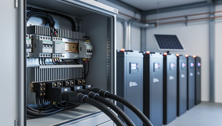
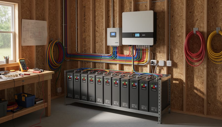
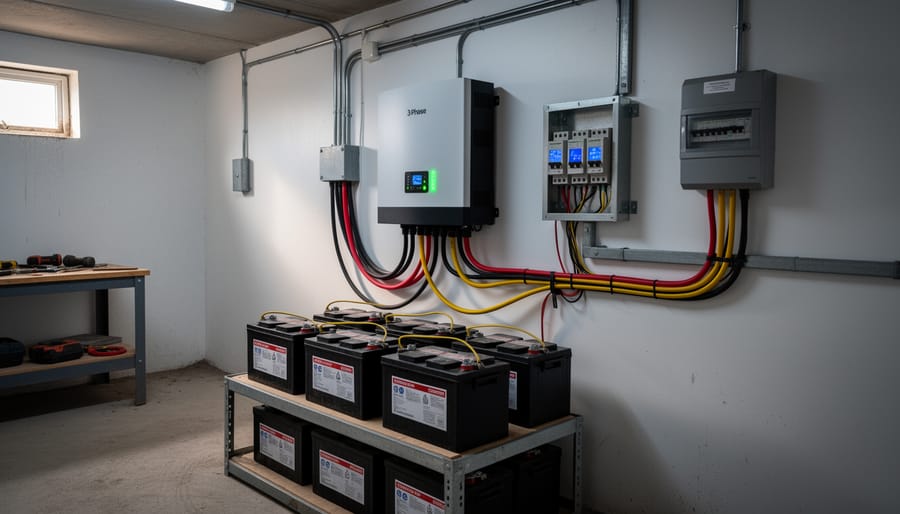
A real off-grid workshop scene helps readers visualize what a 3-phase battery inverter installation looks like in practice.
When You Actually Need a 3-Phase System
Most DIYers don’t need a 3-phase system. Let me be blunt: if you’re powering an RV or a small cabin with basic lights, a fridge, and maybe a laptop, single-phase is the way to go. It’s simpler, cheaper, and perfectly adequate for loads under 5-7 kW.
So when does 3-phase make sense? Three scenarios pop up repeatedly in my conversations with hobbyists.
First, you’re running heavy workshop equipment. If your off-grid workshop has a table saw, air compressor, or welding equipment designed for 3-phase power, you’ll either need a 3-phase inverter or expensive phase converters. Industrial motors run more efficiently on 3-phase, and trying to retrofit them for single-phase often isn’t worth the headache.
Second, your total continuous load exceeds 8-10 kW. At that power level, 3-phase systems distribute current more evenly across three lines instead of forcing everything through two. This means you can use smaller gauge wire for the same power output, and your inverter runs cooler because no single phase carries the full load.
Third, you’re planning significant expansion. I’ve watched friends outgrow single-phase systems within two years, then face costly upgrades. If you know you’ll eventually add an electric water heater, HVAC system, or multiple large appliances to your off-grid cabin, starting with 3-phase saves money long-term.
Here’s my rule of thumb: crunch your numbers honestly. Add up the wattage of everything you’ll run simultaneously, not just what you own today. If that total stays below 7 kW and you don’t have inherently 3-phase equipment, stick with single-phase. You’ll thank yourself during installation.
Tools, Equipment, and Materials You’ll Need
Choosing Compatible Battery Types
Not all battery chemistries play nicely with 3-phase inverter systems, and choosing the wrong type can lead to poor charging efficiency or even damage. The good news? Most modern 3-phase inverters support multiple battery types through programmable charge profiles.
Lithium iron phosphate (LiFePO4) batteries are the premium choice for 3-phase systems. They handle the higher currents typical in three-phase charging without breaking a sweat, offer faster charge rates, and don’t need the complex multi-stage charging that lead-acid types require. You’ll set your inverter to a simple bulk charge around 14.4V per battery module and a lower float voltage (typically 13.6V). The main catch? Upfront cost and ensuring your inverter’s battery management system can communicate with the lithium BMS.
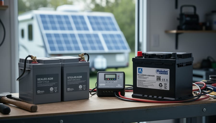
For budget-conscious DIYers, sealed AGM vs lead acid batteries both work fine with 3-phase charging. AGMs are more forgiving, they tolerate the occasional charging hiccup and don’t require ventilation for hydrogen gas. Standard flooded lead-acid batteries cost less but demand precise voltage regulation during the absorption stage and proper ventilation since they release gas during charging. Both need a three-stage charge profile: bulk at 14.4-14.8V, absorption held for 2-4 hours, then float at 13.2-13.8V depending on temperature.
Whatever chemistry you choose, verify your inverter has a preset profile for it or allows custom programming. Mismatched charge voltages will either undercharge (reducing capacity) or overcharge (shortening battery life). Check the battery manufacturer’s spec sheet and match those numbers in your inverter’s settings menu.
Critical Safety Warnings Before You Start
Before you touch a single wire, understand that 3-phase systems operate at significantly higher voltages and currents than typical household single-phase setups. What feels manageable in a 120V circuit becomes potentially lethal when you’re dealing with three lines of 208V or 240V simultaneously feeding a large battery bank. If you’ve never worked with 3-phase power before, this is not the project to learn on without proper training or supervision from someone experienced.
Warning: Working with 3-phase inverter systems combines high-voltage AC power with high-current DC battery banks, both capable of causing fatal electric shock, arc flash burns, or fire. If you’re uncertain about any electrical connections or uncomfortable working with live circuits, hire a licensed electrician familiar with solar installations.
Always wear insulated gloves rated for the voltages you’re handling, safety glasses to protect against arc flash, and closed-toe shoes with rubber soles. Remove all jewelry, especially metal rings and watches that can create short circuits. Work with one hand when possible to reduce the chance of current passing through your chest.
Battery banks deserve special attention because batteries release hazardous gas during charging, particularly hydrogen which is highly explosive. Your installation space needs proper ventilation, never seal batteries in an airtight closet or basement corner. Flooded lead-acid batteries are especially prone to gassing, but even sealed AGM and lithium batteries can vent under fault conditions.
Verify that your main breaker panel is de-energized before making any connections to it, and use a non-contact voltage tester to confirm, don’t just trust the breaker position. Install proper overcurrent protection (fuses or breakers) on both AC and DC sides of the system. Never bypass safety devices to “test quickly” or because they seem inconvenient.
Finally, have a fire extinguisher rated for electrical fires (Class C) within arm’s reach of your work area, and make sure someone else knows you’re working with electrical equipment in case of emergency.
Step-by-Step: Setting Up Your 3-Phase Inverter for Battery Charging
Step 1: Planning Your System Layout and Connections
Before you touch a single wire, grab some graph paper or fire up a simple drawing app, you’ll save yourself headaches and potentially dangerous mistakes. I learned this the hard way when I tried to “wing it” on my first 3-phase setup and ended up rerouting cables twice because I hadn’t accounted for proper clearances.
Start by sketching your component locations. Your inverter needs to go within 10 feet of your battery bank if possible, longer DC cable runs mean voltage drop and wasted power. Mark where your batteries will sit (ideally a cool, ventilated area away from living spaces), then position the inverter somewhere with good airflow and away from direct sunlight. Note the exact distances between components.
Next, verify compatibility by checking spec sheets. Your inverter’s DC input voltage range must match your battery bank voltage, a 48V battery bank won’t work with a 24V inverter, no matter how you wire it. Check that your solar panel array voltage falls within the inverter’s MPPT input range, too. Write these numbers down.
For cable sizing, measure the actual route cables will take, not straight-line distances. Add 20% extra for bends and connections. Use a voltage drop calculator (or the 3% rule of thumb) to determine proper gauge, undersized cables get hot and waste energy. For a 48V system pulling 100 amps, you’re looking at 2/0 AWG or larger for runs over 5 feet.
Double-check phase connections match if you’re connecting to existing 3-phase equipment.
Step 2: Mounting and Grounding the Inverter
Secure your 3-phase inverter to a sturdy wall or equipment rack using the manufacturer’s mounting brackets. Choose a location with at least 12 inches of clearance on all sides, these units generate serious heat during charging cycles, and restricted airflow causes thermal shutdowns or worse. I learned this the hard way when my first inverter hit 140°F in a cramped closet and tripped offline repeatedly.
Mount the inverter vertically at eye level if possible. This makes it easier to read the display and access terminals during configuration. Use vibration-dampening washers if you’re mounting to metal studs, as the internal fans and switching components can transmit noise through rigid connections.
Grounding comes next and it’s non-negotiable. Run a minimum 6 AWG bare copper wire from the inverter’s ground lug directly to your home’s main grounding electrode or ground rod. Three-phase systems carry balanced loads across three hot conductors, but ground faults can still occur on any phase. A solid ground path protects you and your equipment.
If you’re connecting to your main electrical panel, verify your local codes allow DIY work on panels, many jurisdictions require licensed electricians for this step. You’ll typically run three hot wires, a neutral, and ground from the inverter’s AC output to dedicated breakers in the panel. Size these breakers according to your inverter’s maximum output current, which you found in Step 1.
Double-check all mounting hardware is tight before moving to wiring.
Step 3: Wiring the Battery Bank to the Inverter
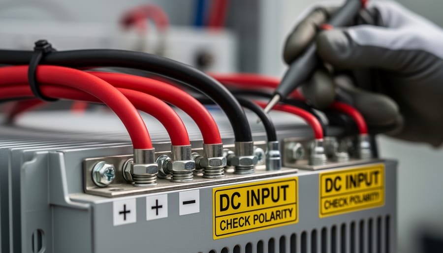
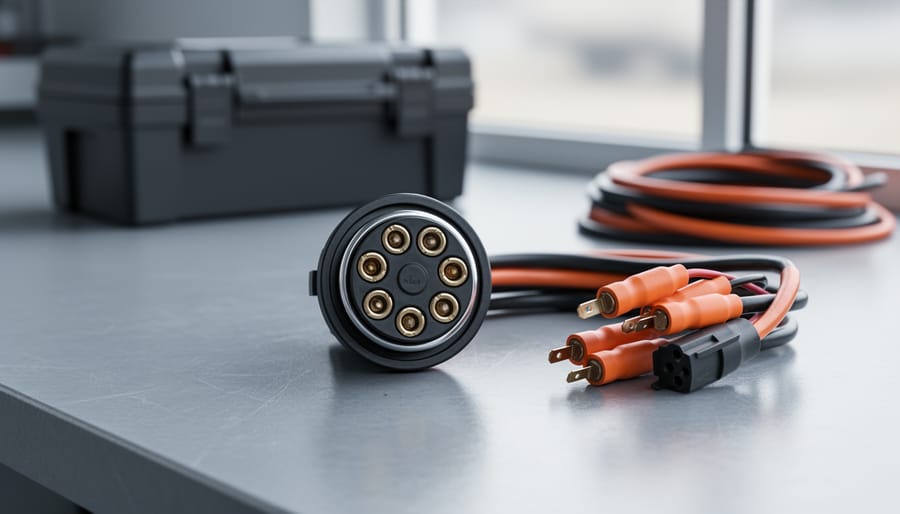
Close-up cable details emphasize the importance of proper DC connections, polarity checks, and secure terminations in a 3-phase battery inverter setup.
Now comes the hands-on part where precision matters most. Making the DC connections between your battery bank and the 3-phase inverter requires careful attention to cable sizing, proper fusing, and triple-checking polarity before you flip any switches.
Start by measuring the physical distance from your battery terminals to the inverter’s DC input posts. Add 10% for slack and bends. For a 48V system pulling 100A continuous, you’ll need at least 2/0 AWG cable to keep voltage drop under 2%. Don’t skimp here, undersized cables generate heat and waste power. I’ve seen melted insulation from folks who thought 4 AWG would “probably be fine” for a 200A draw.
Install an appropriately rated fuse or DC circuit breaker within 18 inches of your battery positive terminal. This protects against catastrophic shorts. For lithium batteries at 100A continuous draw, use a 125A to 150A fuse. Lead-acid systems might need different ratings based on your lead-acid voltage charts and discharge profiles.
Strip about half an inch of insulation from each cable end. Crimp on properly sized lugs, don’t twist bare wire onto terminals. Connect the negative cable first, then positive. This reduces spark risk. Torque battery terminal bolts to manufacturer specs, typically 10-15 foot-pounds for larger posts.
Before connecting to the inverter, use a multimeter to verify polarity at the cable ends. Red lead to red cable should show positive voltage relative to black. Mark both cables clearly with red and black tape near the inverter end.
Finally, connect to the inverter’s DC terminals, negative first again, and torque those connections firmly. Loose connections create resistance, heat, and potential fire hazards.
Step 4: Configuring Charging Parameters
Now comes the part where most DIYers get nervous, punching numbers into the inverter’s settings menu. Don’t worry, it’s less intimidating than it looks once you understand what each parameter actually does for your batteries.
Your 3-phase inverter’s charge controller uses a three-stage charging profile: bulk, absorption, and float. Think of it like filling a water tank. Bulk charging pours current in fast until the batteries hit about 80% capacity. Absorption holds a steady voltage to top them off slowly, like the last 20% that needs gentle pressure. Float maintains them at full charge without overcharging.
Start by locating your inverter’s programming interface, usually a display panel or software connection. You’ll need your battery manufacturer’s spec sheet because these voltages vary by chemistry.
For a 48V lithium battery bank, typical settings look like this: bulk voltage at 57.6V, absorption at 57.6V for 30 minutes, and float at 54.4V. AGM batteries at the same voltage might want 57.6V bulk, 57.6V absorption for 2-3 hours, and 54.0V float. Flooded lead-acid needs slightly higher voltages to compensate for sulfation, around 58.4V bulk and absorption, 54.8V float.
Temperature compensation matters too. If your inverter offers it, enable it for lead-acid batteries (typically -3mV per cell per degree Celsius). Lithium batteries usually don’t need temperature compensation in their bulk range, but check your manufacturer’s guidelines.
Set your maximum charge current to match your battery’s specs, often 0.5C for lead-acid (half the amp-hour capacity) or up to 1C for lithium. A 200Ah battery bank would charge at 100A maximum for lead-acid, 200A for lithium if the cells allow it.
Double-check every number before saving. One decimal point error can wreck a battery bank.
Testing and Verifying Your Charging Setup
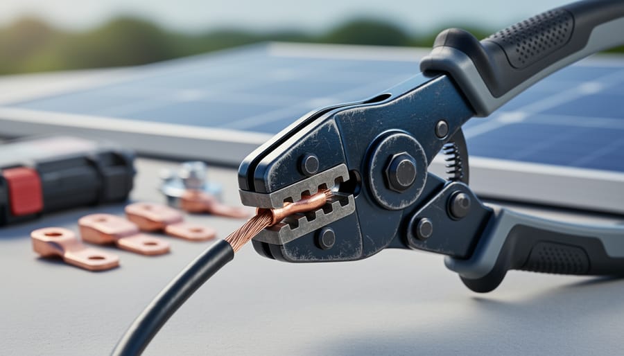
Testing imagery reinforces careful measurement and verification before relying on the charging system.
Before you flip that main breaker, take a deep breath. First-time power-up is where careful planning meets reality, and you want to catch any issues before they become expensive lessons. I remember standing in front of my first 3-phase system with a multimeter in hand, double-checking every connection one last time, it’s normal to feel a bit nervous, and that caution will serve you well.
Start with your batteries completely disconnected from the inverter. Power up just the inverter itself from your solar panels or AC input (if it has pass-through capability) and verify it initializes without error codes. Most modern inverters have an LCD display that’ll show status messages, you’re looking for a clean boot with no fault warnings. If everything looks good, power down and make your battery connections, ensuring terminals are tight and polarity is absolutely correct.
When you’re ready to check inverter charging for the first time, power the system back up and watch closely. Within a few seconds, you should see the charge controller activate and current begin flowing to your battery bank. Here’s what to verify during those critical first minutes:
Battery voltage rising gradually (not jumping erratically)
Charging current displayed on inverter matches your configured bulk rate
All three phases showing balanced load (within 5-10% of each other)
Battery temperature staying below 45°C (113°F)
No unusual sounds, hums, buzzes, or clicking from connections
Inverter display showing “charging” or “bulk” mode, not error states
Use a clamp meter on each phase wire to confirm balanced current draw, if one phase is pulling significantly more than the others, you’ve got a wiring issue to address. Normal readings for a 5kW system might show 7-8 amps per phase during bulk charging with full sun. Your battery voltage should climb steadily from its resting voltage toward the bulk setpoint you programmed earlier.
Stay present for at least the first 30 minutes of charging. If voltages shoot up too quickly or charging current stays near zero despite full sun, power down immediately and recheck your configuration settings.
Optimizing Charging Performance and Troubleshooting Common Issues
Using the Spheral Solar Calculator for Your System
I’ve built a power system calculator specifically for folks planning solar setups like yours. Plug in your expected loads, battery capacity goals, and available solar panel wattage, and it’ll recommend appropriate inverter sizes, including whether you actually need 3-phase capability. The calculator accounts for charging efficiency losses and seasonal variations, so you’re not guessing at specs. It’s saved me from undersizing components more than once. If you’re still having issues after setup, the troubleshooting guide can help fix inverter not charging problems common in DIY installations. Just enter your real-world usage patterns rather than theoretical maximums, you’ll get more practical results that way.
Frequently Asked Questions
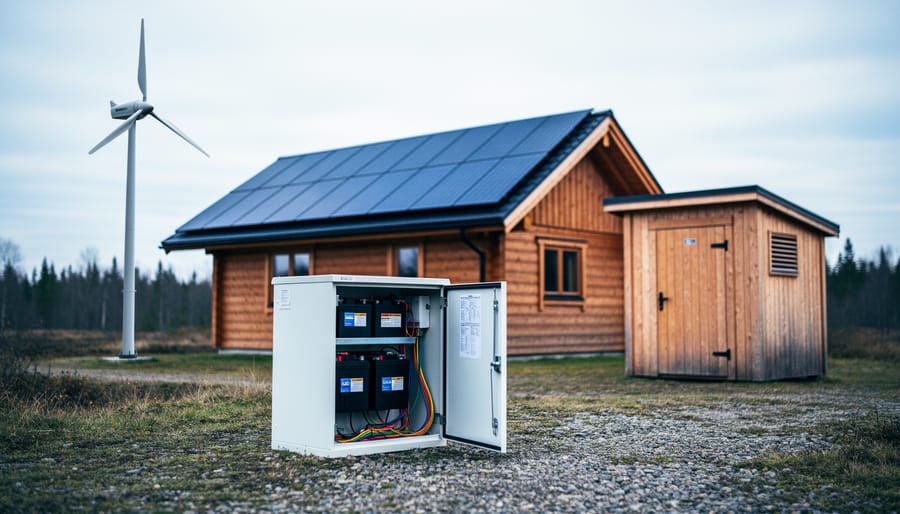
A dimly lit installation scene conveys how a 3-phase inverter system operates reliably in real off-grid conditions.
Is a 3-phase system significantly more expensive than single-phase?
Yes, expect to pay 30-50% more for a 3-phase inverter compared to an equivalent single-phase unit, plus additional costs for specialized wiring and potentially upgrading your electrical service. However, for systems above 10kW, the improved efficiency and component longevity often justify the upfront investment over the system’s lifetime.
Can I convert my existing single-phase solar system to 3-phase?
It’s technically possible but rarely practical for DIYers. You’d need to replace the inverter, rewire much of the system, and possibly upgrade your electrical panel, essentially rebuilding most of the setup. For most homeowners, it makes more sense to design for 3-phase from the start or stick with scaling up single-phase capacity.
How often do 3-phase inverters need maintenance?
Beyond the standard battery maintenance your system already requires, 3-phase inverters themselves need minimal attention, typically just visual inspections every six months to check for loose connections, dust buildup on cooling vents, and firmware updates once or twice a year. The additional phase doesn’t meaningfully increase maintenance compared to single-phase units.
Will a 3-phase inverter work with my existing battery bank?
Most likely yes, as long as your batteries are configured for the voltage your inverter expects (typically 48V for larger systems) and can handle the charging current. The number of phases affects how the inverter converts DC to AC, not the fundamental battery chemistry compatibility, just verify your battery type appears in the inverter’s supported list before purchasing.
These are the questions I get asked most often after someone’s read through the technical setup instructions and is trying to decide whether to take the plunge. The cost question especially comes up because people see the price tag and wonder if they’re overpaying for something unnecessary.
Here’s something worth knowing that doesn’t fit neatly into a single question: 3-phase systems can actually be easier to troubleshoot in some ways because you’ve got three separate phases to test. If one phase is acting up, you can isolate it and keep the system partially operational while you diagnose the problem. With single-phase, you’re often dealing with all-or-nothing situations.
One concern I don’t see mentioned enough is noise. Three-phase inverters often run quieter than equivalent single-phase units because the power delivery is smoother and the components don’t work as hard. If your inverter is near living spaces, that steady hum instead of a louder buzz makes a real difference. I learned this the hard way when I installed a beefy single-phase unit in my workshop and spent the next month getting annoyed every time I was trying to have a conversation in there.
The compatibility question deserves a bit more context too. Your existing charge controller settings won’t automatically transfer to a new 3-phase setup, you’ll need to reconfigure everything for your specific battery chemistry. Don’t assume you can just plug and play based on what worked with your old inverter. Take an afternoon to carefully input the correct bulk, absorption, and float voltages for your batteries, and verify them against the manufacturer’s specs rather than trusting defaults.
Setting up a 3-phase battery inverter system isn’t the simplest weekend project, and I won’t pretend otherwise. You’re dealing with higher voltages, more complex wiring configurations, and charging parameters that demand attention to detail. But here’s what I’ve learned after years of helping DIYers tackle these systems: if you can follow instructions carefully, double-check your work, and respect the electricity you’re working with, you can absolutely do this yourself.
The difference between a successful installation and a frustrating one comes down to preparation. Take the time upfront to plan your layout properly, gather the right equipment, and understand why each safety step matters. Don’t skip the grounding. Don’t rush through the configuration settings. And for goodness’ sake, verify your connections before you flip that switch for the first time. Those extra hours spent measuring twice really do save you from having to troubleshoot problems later.
I’ve seen hobbyists with no formal electrical training successfully build robust 3-phase charging systems for their workshops and off-grid cabins. The key was patience and willingness to learn as they went. You’re now equipped with the same knowledge they used.
Got questions as you work through your own setup? Run into something unexpected? Drop a comment below. The Spheral Solar community thrives on sharing real-world experiences, and your insights might help the next person tackling their first 3-phase project. We’re all learning together here.
How useful was this post?
Click on a star to rate it!
Average rating 0 / 5. Vote count: 0
No votes so far! Be the first to rate this post.
We are sorry that this post was not useful for you!
Let us improve this post!
Tell us how we can improve this post?
charlesnoble
Here at Spheral Solar, I’m a hands-on solar power enthusiast, constantly exploring and experimenting with DIY solutions. I’m dedicated to sharing my discoveries, insights, and even the bumps I hit along the way, all in the pursuit of a more sustainable future.
How to Wire a 7-Way RV Plug: Step-by-Step Diagram… by Charlesnoble September 12, 2026 Wiring a 7-pin RV plug correctly connects your tow vehicle to your trailer’s lights, brakes, and auxiliary power in about 45 minutes with basic hand tools and careful attention to the color-coded wire standard. The diagram follows a specific layout mandated by the RV Industry Association: each pin controls a…
How to Use an 8 Wire Crimper for Solar Panel and… by Charlesnoble September 24, 2026 Crimping 8-gauge wire correctly takes about 2 minutes per connection once you’ve got the hang of it, but those two minutes make the difference between a solar installation that lasts 25 years and one that fails in the first storm. An 8-gauge wire crimper is a heavy-duty hand tool designed…
5 Sources of Electrical Energy Every Solar DIYer… by Charlesnoble July 1, 2026 Electricity powers our homes from five main sources: solar panels, wind turbines, hydroelectric generators, fossil fuel generators, and battery storage systems. If you’re building a reliable off-grid setup or backing up your solar array, understanding how these sources work together transforms a single-point-of-failure system into resilient, year-round power. I learned…
Why Two Solar Panels Beat One Every Time (Parallel… by Charlesnoble June 22, 2026 Connect your panels to a charge controller or battery system by running positive terminals to positive and negative to negative. This parallel configuration doubles your available current (amperage) while keeping voltage the same, which is exactly what you need when your system demands more power than a single panel can…
6 Best Solar Spot Lights of 2026, Tested and Reviewed by Charlesnoble August 8, 2026 After testing dozens of solar spotlights in real-world conditions throughout 2026, the AloftSun Solar Motion Sensor Outdoor Lights emerged as the top overall choice for most homeowners, thanks to its reliable performance and versatility across different landscape lighting scenarios. But picking the right solar spotlight depends entirely on what you’re…
AGM vs. Lead Acid Batteries: Which Is Better for… by Charlesnoble July 23, 2026 AGM batteries outperform traditional flooded lead acid batteries in nearly every practical measure that matters for solar installations, but whether that performance justifies their 50-100% higher upfront cost depends entirely on how hands-off you want your system to be and how often you’ll cycle the battery deeply. After running both…
Subscribe for handpicked DIY projects, exclusive tips, and giveaways.
Low voltage circuit protection in DIY solar systems boils down to matching the right fuse or breaker to your wire size and expected current, not to the capacity of your battery bank or inverter. Most fires and equipment failures happen when people oversize protection devices, thinking bigger is safer, when the opposite is true. Your… Read more: How to Size Low Voltage Circuit Protection for Your DIY Solar System
Crimping 8-gauge wire correctly takes about 2 minutes per connection once you’ve got the hang of it, but those two minutes make the difference between a solar installation that lasts 25 years and one that fails in the first storm. An 8-gauge wire crimper is a heavy-duty hand tool designed to cold-forge lugs and terminals… Read more: How to Use an 8 Wire Crimper for Solar Panel and Battery Connections
Building a solar powered outdoor table takes about 8 to 12 hours and requires basic woodworking skills plus some familiarity with electrical connections. You’ll mount solar panels directly onto a custom-built or modified outdoor table, wire them to a charge controller and battery system housed underneath, and add USB ports or AC outlets for charging… Read more: How to Build a Solar Powered Outdoor Table for Your Camping Setup